EPSON Stylus Pro 7000 Revision B
Operating Principles Description of Components 65
2.2.3 Maintenance Assembly
The maintenance assembly for the SP 7000 is similar to the maintenance
assembly in the EPSON Stylus Pro 9000. If you are not familiar with the SP
9000, see the following for a detailed description.
See Figure 2-5 on page 59 for an illustration of the cleaning. The main
components are:
Pump Assembly (head cleaner)
Pump Motor (stepping motor)
Cap Assembly (B head/C head independent)
Flushing Box
Waste Ink pads
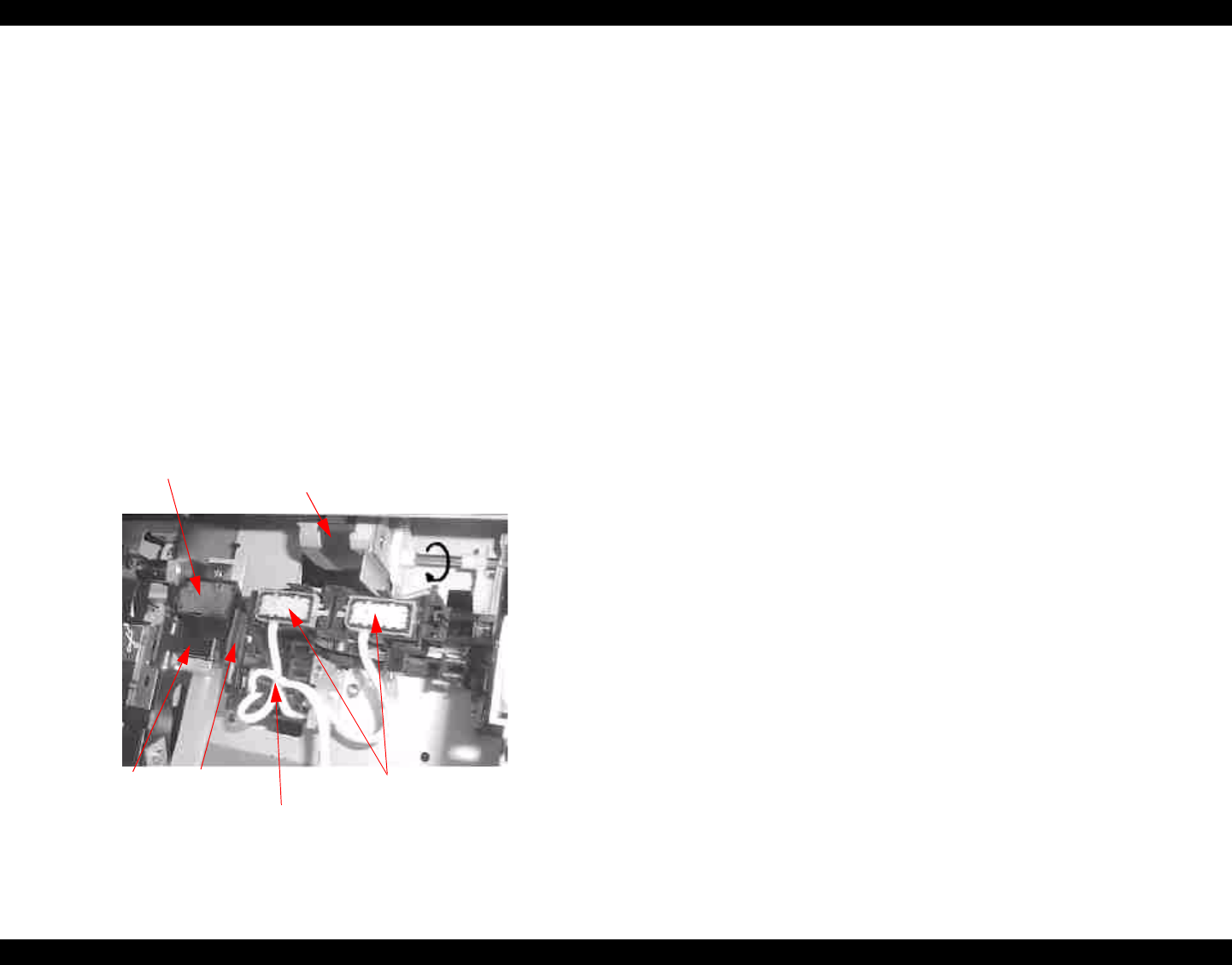
The cleaning mechanism components are installed above the subframe and
some are fixed on the main frame as shown below.
Figure 2-13. Cleaning Mechanism Components
Pump assembly (head cleaner)
When the head is in the capped position (valve closed), the pump motor
creates a vacuum that sucks ink from the nozzles. This is used for
removing ink from the nozzles and nozzle plate, initial ink charge, as well
as cleaning. The waste ink flows through two small tubes to the waste ink
pads.
Head cleaner
The head cleaner has felt on one side and rubber on the other, and is used
to wipe or rub off ink and foreign materials from the nozzle surface.
Pump motor
Clockwise rotation = pump assembly drive for cleaning and so on
Counter clockwise rotation = platen gap adjustment
Cap assembly (one pad for each printhead)
When not printing, the printheads (should) rest on the cap assembly to
make sure the nozzles don’t clog. Also, the printheads are in the capped
position during ink charging, cleaning, and so on.
Flushing box
Flushing (dummy printing) is performed over the flushing box, and the
flushed ink flows through the large diameter tube to the waste ink pads.
Flushing fires a little ink to remove ink that may be drying on the nozzle
surface; performed in between print jobs and sometimes during long
print jobs.
Waste ink pads
The waste ink pads absorb ejected ink through the pump assembly ink
tubes and the flushing box tubes.
When the pads near full, the LCD displays Maintenance Call 0100. When
the pads are completely full, the LCD displays Service Call 00000100. The
pads must be replaced at this time.
Pump
Motor
Pump
rotation = CW
Flushing box
Cap Assembly
Pump Assembly
Head
Cleaner
CR Lock


