EPSON Stylus Pro 7000 Revision B
Disassembly & Assembly Disassembly Flow 143
4.2.3.13 Removing the Maintenance Assembly
1. Remove the R Side Cover as described in “R Side Cover Removal” on
page 114.
2. Remove the Rear Cover as described in “Rear Cover Removal” on
page 118.
3. Disconnect the harness for the Pump Motor Assembly from its connector
on the main board, and take the harness out from the hole in the R side
frame.
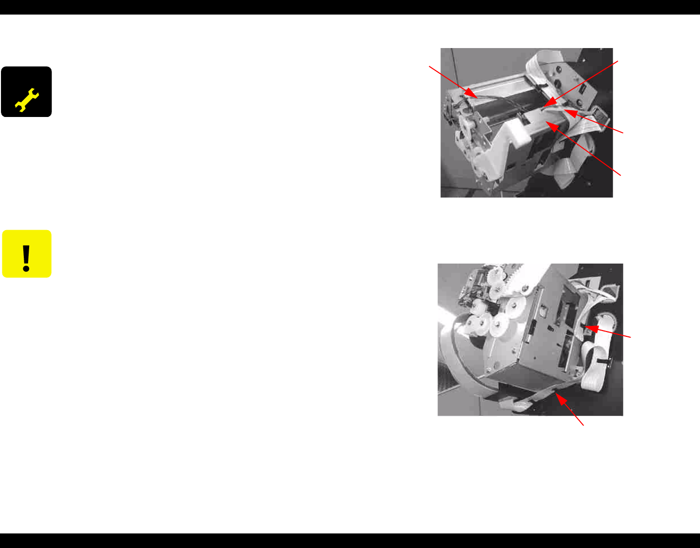
4. Release the one Pump Motor Assembly harness and two sensor
harnesses from the clamp on the Maintenance Base Assembly.
Figure 4-63. Removing the Harnesses - 1
5. Release the panel FFC and CR FFC from the cable clamps at the back and
bottom of the Maintenance Base Assembly, respectively.
Figure 4-64. Removing the Harnesses - 2
ADJUSTMENT
REQUIRED
If you replace the waste ink absorbers because the service call
error 0000100 occurs, you need to replace the specified parts*
in the Maintenance Assembly. After replacing them, be sure to
initialize the following counters:
Waste ink counter
Cleaning unit counter
* Parts to be replaced: Pump Motor, Cap Assembly, Pump
Assembly, Cleaner Head, and Flushing Box Assembly
NOTE: The above mentioned parts are available as a kit:
[Description] MAINTENANCE KIT
[Parts code] 1054038
CAUTION
When you replace the Maintenance Assembly, ink may spill
from the ink tube connected to the pump assembly. Therefore,
wipe the ink around the ends of the ink tubes preliminarily.
Two Sensor
Harnesses
Clamp
Pump Motor
ASSY.
Harness
Maintenance
Base
Clamp
(for Panel
FFC)
Clamp (for CR
FFC)


