EPSON Stylus Pro 7000 Revision B
Disassembly & Assembly Disassembly Flow 147
4.2.3.15 Removing the Cap Assembly
1. Remove the Maintenance Assembly as described in “Removing the
Maintenance Assembly” on page 143.
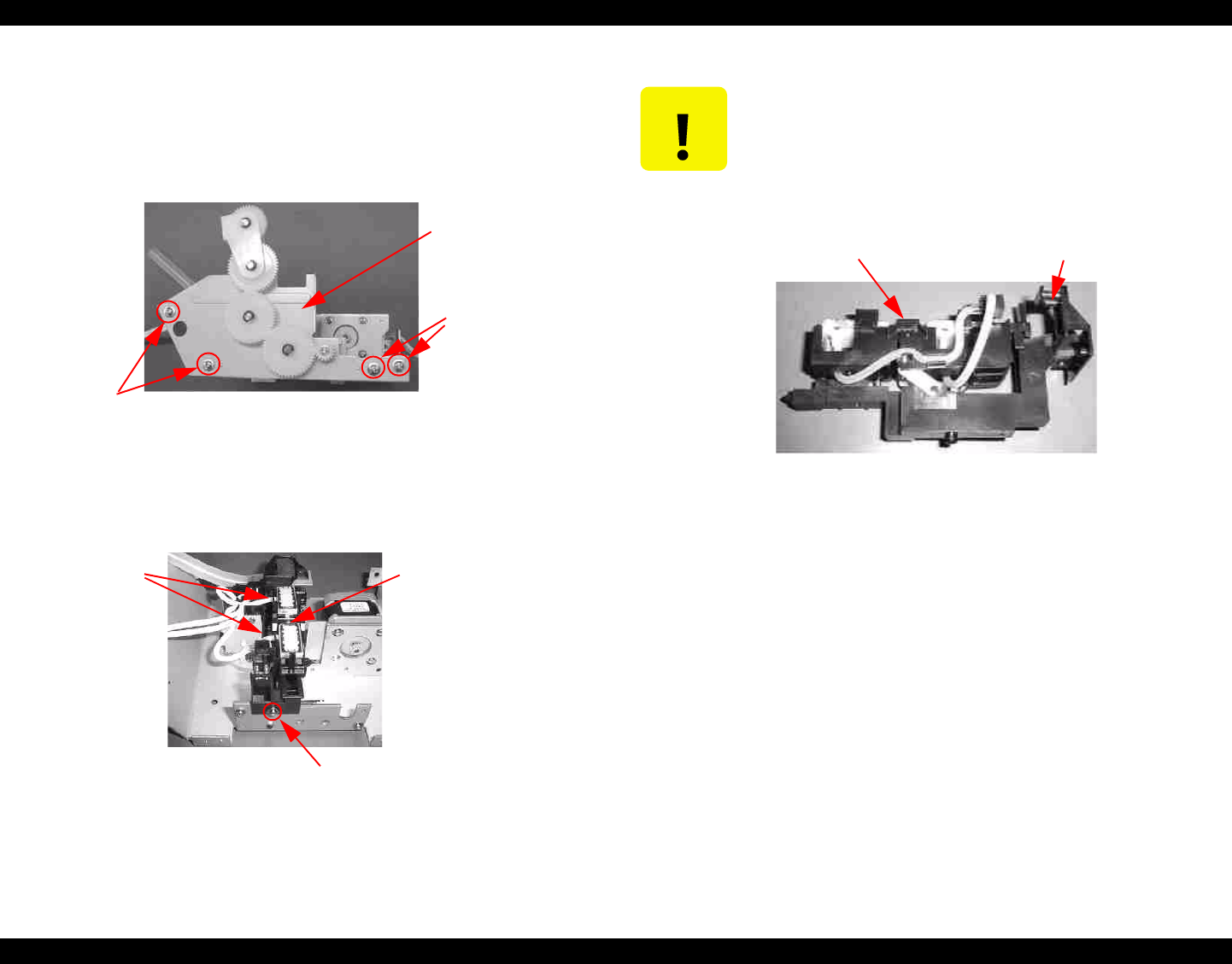
2. Remove the four (CUPS M4x3) screws securing the R Side Frame Sub
Assembly and remove the R Side Frame Sub Assembly.
Figure 4-70. Removing the R Side Frame Sub Assembly
3. Remove the one (CUPS M3x6) screw securing the Cap Assembly,
disconnect the two tubes from the Pump Assembly, and remove the Cap
Assembly.
Figure 4-71. Removing the Cap Assembly
Figure 4-72. Cap Assembly
R Side Frame
Sub Assembly
Screws
(M4x6)
Screws
(M4x6)
Cap
Assembly
Screw
(M3x6)
Tubes connect
here.
CAUTION
Check for the points below when removing/mounting the Cap
Assembly.
Push the cap part down to the valve part and check that
the cap part rebounds with spring force.
Check that the valve part is not dislocated.
Cap part
Valve
part


