EPSON Stylus Pro 7000 Revision B
Disassembly & Assembly Disassembly Flow 134
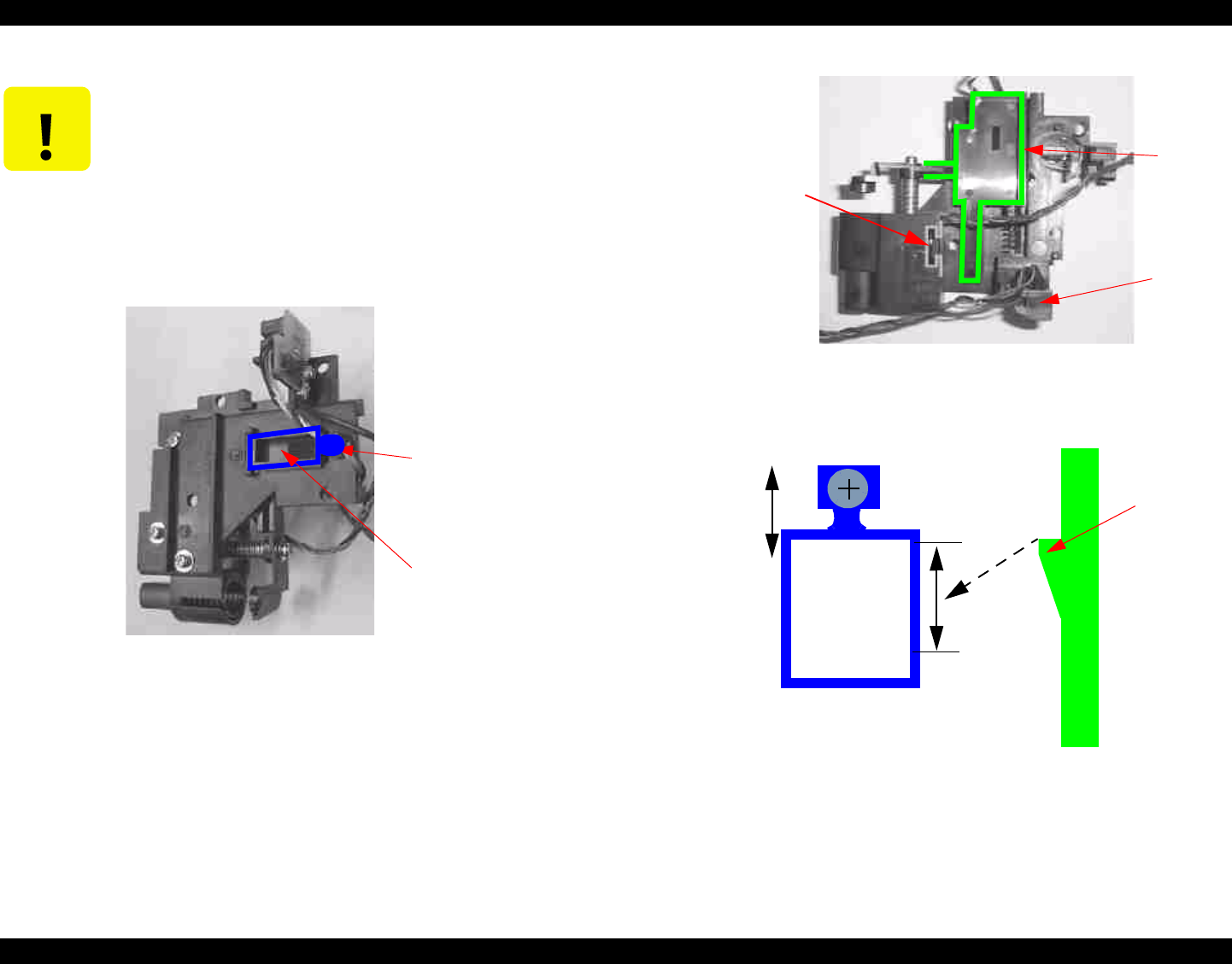
Figure 4-43. Cutter Housing Outer Face
Figure 4-44. Cutter Housing Inner Face
Figure 4-45. Cutter Height Determination (factory adjustment)
NOTE: The above cutter guide height adjustment is for your
information and should not be necessary under normal
circumstances.
CAUTION
Do not tighten the four screws securing the cutter housing too
tightly. They can pull out the female screws on the carriage
side, which warps the cutter housing. Since the encoder
sensor is attached to the cutter housing, the encoder may have
problems (trust me!).
If you run into the following or similar errors after replacing
the cutter housing, loosen the screws a little and try again.
Service Req. 0001000F
Service Req. 00010006
Cutter
guide
height lock
Cutter
guide
P_EDGE
sensor
Hole shaped like
“T”; slide over
corresponding part
of carriage to
secure the cutter
housing
Cutter
guide
Cutter guide height lock
Cutter guide
The up/down
movement range is
limited by the
frame of the cutter
guide height lock.
Cutter height
determined and
then screw
secured in factory
Faces the ink
holder side


