EPSON Stylus Pro 7000 Revision B
Operating Principles Printer Mechanism Operation Outline 69
2.3 Printer Mechanism Operation Outline
This section describes the various parts of the printer mechanism and how
those parts work.
2.3.1 Carriage Mechanism
The carriage speed is determined by a software servo system. This software
servo is a closed-loop system where the CR motor (a DC motor) must provide
constant torque to keep the carriage speed even. For this purpose a timing
fence (or step ruler) and an encoder sensor are employed to measure the
carriage speed/location and to provide feedback to the motor controller
accordingly.
Print Control
The carriage speed during printing is described below.
Note: Due to the carriage’s quick acceleration process, even after the
heads reach and maintain normal speed, they are not stable enough to
print for the next 10mm.
Stop Control (stop position)
The encoder determines the carriage position by counting the dark
stripes on the Step Ruler. When the carriage reaches the
predetermined position (depends on paper width), the carriage stops.
To make sure the carriage has come to a complete stop, the printer
checks the encoder for a certain time (in-position time-out) to make
sure no signal is generated.
CR Motor Abnormality Detection
The software servo sends a series of pulses to the CR Motor to drive
the carriage a certain distance (depends on current operation, paper
size, and so on). At the same time the encoder measures the distance
the carriage travels. If the position of the carriage according to the
Software Servo is different from the position according to the
encoder, a fatal error occurs (Service Call 00010005).
See page 60 for details on carriage sensors and other parts.
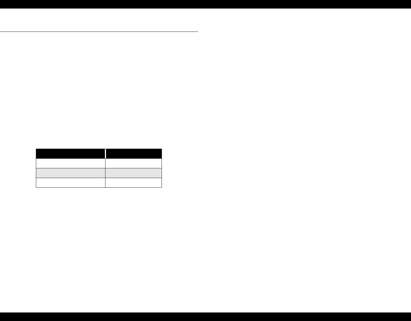
Table 2-3. Print Speed
Print Mode Carriage Speed
720dpi & Normal M/W 200cps
4 Pass FOL printing 300cps
unidirectional 400cps


