


139
Controlling Cameras
Chapter 3 Operations
You can also reset the camera by holding down the Shift button and pressing
the numeric 0 button.
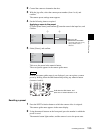
About Camera Tallies
When the camera supports the camera tally function (BRC series, etc.)
The camera tally lamp lights when the input from the camera is being used as
program output.
Multiple settings are possible for the [Video Input Assign] [Control] setting.
In this case, the camera tally lights when the video from any of the source viewers
for which the [Control] setting is made is being used for program output.
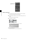
When using CCU, etc.
If the FACTORY USE connector of the unit is connected to the tally connector
of a CCU (camera control unit), the tally lamp lights for any camera that is
assigned to a PGM selection button or NEXT selection button on the front panel,
as long as video from that camera is being used as program output (the button
lights red).
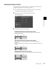
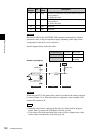
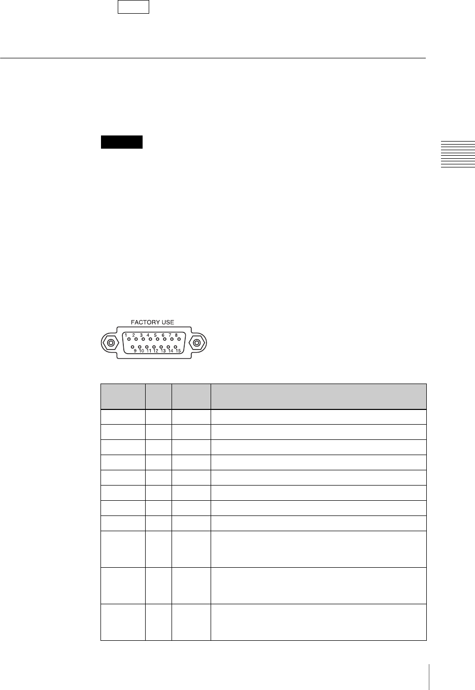
Specifications of the FACTORY USE Connector
The specification of each pin is as shown below.
Note
Caution
Pin
Number
I/O
Signal
Name
Description
1 I - Unused
2 I - Unused
3 I - Unused
4 I - Unused
5 I - Unused
6 I - Unused
7-GNDGROUND
8-GNDGROUND
9 O GPO0 GIP OUT1: Controls the tally of the camera assigned to
source number 1.
On: GND; Off: Open
10 O GPO1 GIP OUT2: Controls the tally of the camera assigned to
source number 2.
On: GND; Off: Open
11 O GPO2 GIP OUT3: Controls the tally of the camera assigned to
source number 3.
On: GND; Off: Open