


Chapter 3 Operations
140
Controlling Cameras
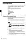
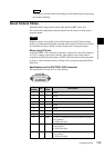
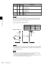
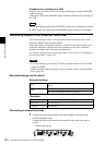
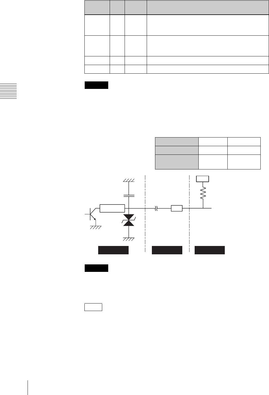
Because the GPO of the FACTORY USE connector on the unit has a built-in
protection circuit, it may not operate properly depending on the input circuit
configuration of the device to be connected.
See the diagram below, make the cables.
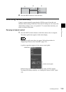
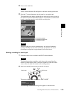
When using the CCU, the camera tally control is possible for the camera assigned
to source number 1 to 5. When the camera is assigned to source number 6, the
camera tally cannot be lit.
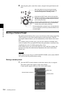
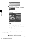
• When the video from a camera with the tally lit is being used for program
output, then if you press the FTB button, the tally goes off.
• If you open a file on the hard disk in the source viewer assigned to the video
from a camera with the tally lit, the tally goes off.
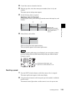
12 O GPO3 GIP OUT4: Controls the tally of the camera assigned to
source number 4.
On: GND; Off: Open
13 O GPO4 GIP OUT5: Controls the tally of the camera assigned to
source number 5.
On: GND; Off: Open
14 - GND GROUND
15 - GND GROUND
Caution
Caution
Notes
Pin
Number
I/O
Signal
Name
Description
AWS-G500
Cable Connected device
10000 pF
100 k ohm
Vcc
R
NOISE FILTER
RSB6.8SFTE
Vz=±5.78 V
~7.82 V
Connected device CCU-D50 HFU-X310
Vcc +9 V +3.3 V
R 510 k ohm None (Short
circuited)
Sample circuit diagram