


19
Names and Functions of Parts
Chapter 1 Overview
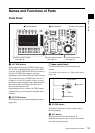
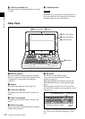
j Jog dial (inner dial)
This dial controls the camera focus and iris.
During file playback, turning this dial plays the
file at a slow speed that corresponds to the speed
at which the dial is turned (page 134, 149).
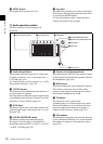
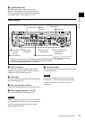
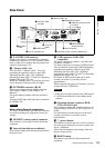
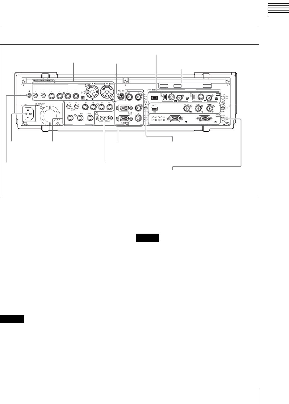
Rear Panel
a VISCA connector
To connect the chain of cameras with VISCA
support to this unit for remote control operation,
connect the VISCA cable (page 50).
b Cable clips
Use these clips to prevent cables from accidentally
disconnecting (page 54).
c Intercom interface connector
Connect an external intercom system (page 155).
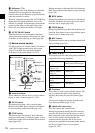
d Power supply connector (~AC IN)
Use to connect to an AC outlet (page 41).
When using a DC-AC inverter, the use of a 50 Hz
(±3%) or 60 Hz (±3%) sine wave is recommended.
Do not use a general-purpose inverter with a
square output waveform.
e Ground terminal
When using this unit, connect the ground terminal
to a grounding lead.
The ground terminal is close to the audio input
connectors, so when connecting the grounding
lead be careful not to touch the audio input
connectors.
AC IN
LINE MIC/LINE
MIX
HEADPHONES
MONI INTERCOM
15
69
RGB PGM
S VIDEO
AUX PGM RGB
I.LINK
S VIDEO
COMPOSITE
S VIDEO
COMPOSITE
S400
RGB RGB
COMPOSITE
MIC/LINE
PUSH PUSH
AUDIO IN
VIDEO IN
AUDIO OUT VIOEO OUT
876543
RRLL
RL
21
21
OFF
ON
SD
OFF
ON
OFF
ON
PC
1
2
3
SDI
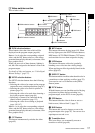
4 Power supply
connector
(~AC IN)
1 Audio inputs
1
VISCA
connector
4 SD video interface module
(see page 21)
6 PC video interface module
(see page 22)
3 Video outputs
(see page 21)
3 Intercom interface connector
2 Audio outputs
(see page 20)
2
Cable clips
5 Ground terminal
5 Serial digital interface
module (option)
(see page 22)
* This figure is when an optional serial digital interface module (BKAW-580)
is installed in slot 2 of the AWS-G500. An SD interface module is installed
in slot 2 of the AWS-G500 at the time of shipment.
Caution
Caution