51
Connections
Chapter 2 Preparations
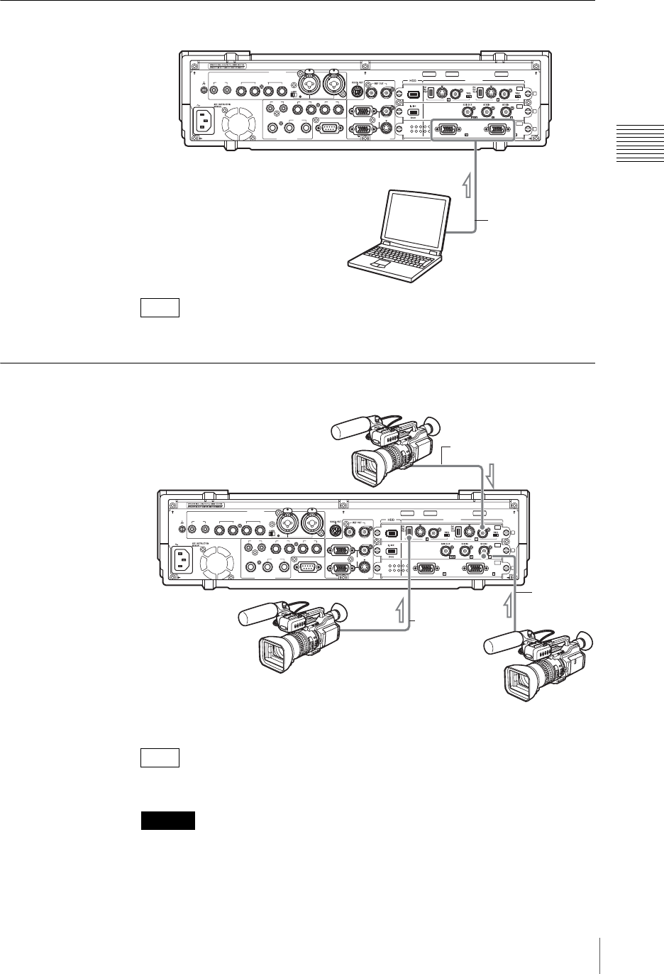
Connecting a Computer (RGB Input)
To reduce the effects of external noise, use a cable with an attached ferrite core.
Connecting a Camcorder
i.LINK cables between 80 cm and 3.5 m (2.5 to 11.5 ft) are recommended.
• The frequency precision of the reference output signal is within 50 ppm. When
building a system that includes devices such as a camera with a Gen Lock
input, be sure to test it thoroughly before use.
• The color frame of the program output signal does not reflect the color frame
sequence of the reference output signal.
Note
Note
Caution
AC IN
LINE MIC/LINE
MIX
HEADPHONES
MONI INTERCOM
15
69
RGB PGM
S VIDEO
AUX PGM RGB
I.LINK
S VIDEO
COMPOSITE
S VIDEO
COMPOSITE
S400
RGB RGB
COMPOSITE
MIC/LINE
PUSH PUSH
AUDIO IN
VIDEO IN
AUDIO OUT VIOEO OUT
876543
RRLL
RL
21
21
OFF
ON
SD
OFF
ON
OFF
ON
PC
1
2
3
SDI
Computer
To RGB input
connectors
RGB cable
AC IN
LINE MIC/LINE
MIX
HEADPHONES
MONI INTERCOM
15
69
RGB PGM
S VIDEO
AUX PGM RGB
I.LINK
S VIDEO
COMPOSITE
S VIDEO
COMPOSITE
S400
RGB RGB
COMPOSITE
MIC/LINE
PUSH PUSH
AUDIO IN
VIDEO IN
AUDIO OUT VIOEO OUT
876543
RRLL
RL
21
21
OFF
ON
SD
OFF
ON
OFF
ON
PC
1
2
3
SDI
DVCAM camcorder
(DSR-PD170, etc.)
For DV connection
BNC cable
To Composite
input connectors
i.Link cable
To DV connectors
For analog connection
BNC cable
For SDI connection


