25
Names and Functions of Parts
Chapter 1 Overview
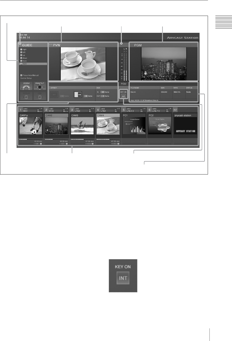
Operation Screen
a Menu display
This displays the top menus (page 30), the INT
material selection menu (pages 79, 161), the
camera guide menu (pages 133, 134), and the
HDD guide menu (page 147).
b Guidance object indication
The color of the guidance object indication has the
following significance.
Amber:when a video subject to camera control
(page 132) and external hard disk control
(page 144) or INT is selected with the NEXT
selection buttons (while the KEY button is not
lit).
Green:when a video subject to camera control and
external hard disk control or INT is specified
with the NEXT selection buttons (while the
KEY button is lit).
Off:when other than a video subject to camera
control and external hard disk control or INT
is specified with the NEXT selection buttons.
c Audio level meter
When monitoring the any of the PGM/AUX1/
AUX2/MIX audio outputs or Pre Fader Listen
(PFL) result, this shows the audio level. An
indication below the meter shows which of PGM/
AUX1/AUX2/MIX or PFL is being monitored.
When the level exceeds the meter range, the
uppermost indicator lights red (page 158).
d KEY ON
The indicator lights red during keying to program
output video. The number (1 to 6) or “INT” of the
source selected for keying appears.
3 Audio level meter
4 Source viewer5 Effect display
3 Streaming display
2 PVW viewer
1 Menu display
1 PGW viewer
2 Guidance object indication
* This example screen shows the streaming settings displayed.
Normally the streaming display cannot be viewed.
4 KEY ON


