


23
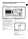
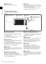
Names and Functions of Parts
Chapter 1 Overview
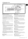
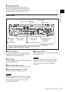
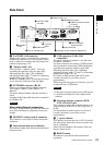
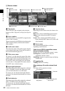
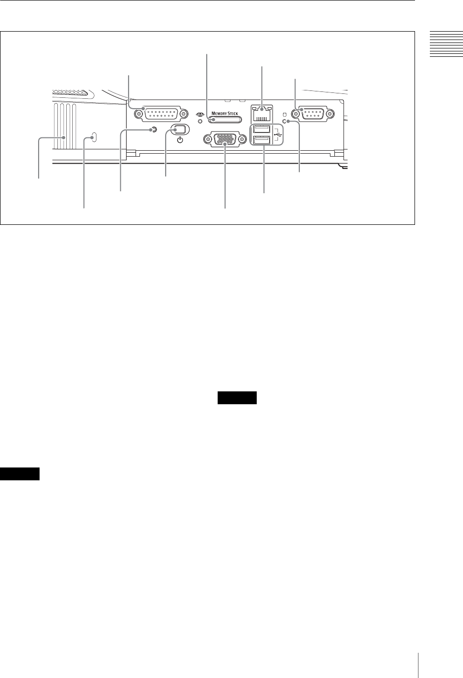
Side Panel
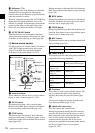
a FACTORY USE connector
Output a tally signal. Connecting this connector
and the tally connector of a CCU (camera control
unit) or other device enables the tally lamp of the
camera to light (page 139).
b “Memory Stick” slot
This slot takes a “Memory Stick.” Use it for
upgrading the operating software (page 200),
importing font files (page 129), exporting/
importing job data (page 173 and 174), importing
graphics files (page 175), etc.
While the “Memory Stick” is being accessed, the
access indicator to the left of the slot lights.
c NETWORK connector (RJ-45)
Connect an external network adaptor or router.
This supports 10Base-T and 100Base-TX
Ethernet.
The green indicator blinks while the network is
active.
An amber LED lights while the unit is connected
by 100Base-TX.
When making Network connections
For safety, do not connect the Network connector
to circuits which may be subjected to excessive
voltage.
d REMOTE (remote control) connector
This connector is provided for future functional
expansion.
e Internal hard disk access indicator
This indicator lights while the internal hard disk is
being accessed.
f USB connectors (USB) (USB
compatible)
The upper connector is number 1, and the lower
connector is number 2.
Use these connectors to connect a USB keyboard.
Also use them for connecting USB flash memory,
upgrading the operating software (page 200),
importing font files (page 129), exporting/
importing job data (page 173 and 174), importing
graphics files (page 175), etc.
For details of the keyboards that can be used,
consult your dealer or your Sony service
representative.
When using the text typing tool software, you can
connect and use a USB mouse.
• These do not support input from a USB camera.
• A USB mouse cannot be used with the main
software.
g Operating monitor connector (RGB
(GUI)) (D-Sub 15-pin)
This connector outputs the operation screen to an
external display at WXGA (1,280 × 800) size, at
60 Hz.
For information on which devices can be used,
consult your dealer or your Sony service
representative.
h 1 (power) button
This button powers the unit on or off. If you hold
down the power button for at least 4 seconds, this
forces a shutdown.
After a forced shutdown, the settings of the unit
may not be preserved.
i RESET button
This button is provided for future functional
expansion.
FACTORY USE REMOTE
RGB
(
GUI
)
RESET
USB
NETWORK
18
15 9
15
96
0 Hole for anti-theft wire
2 “Memory Stick” slot
3 NETWORK connector
4 REMOTE (remote control)
connector
5Internal hard disk
access indicator
6 USB connectors
7 Operating monitor connector (RGB (GUI))
8 1 (power)
button
9 RESET button
1 FACTORY USE
connector
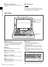
qaVentilation
holes
With the protective panel opened
Caution
Caution