


8-2
Cisco IOS Software Configuration Guide for Cisco Aironet Access Points
OL-30644-01
Chapter 8 Configuring Spanning Tree Protocol
Understanding Spanning Tree Protocol
Understanding Spanning Tree Protocol
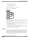
This section describes how spanning-tree features work. It includes this information:
• STP Overview, page 8-2
• Access Point/Bridge Protocol Data Units, page 8-3
• Election of the Spanning-Tree Root, page 8-4
• Spanning-Tree Timers, page 8-4
• Creating the Spanning-Tree Topology, page 8-5
• Spanning-Tree Interface States, page 8-5
STP Overview
STP is a Layer 2 link management protocol that provides path redundancy while preventing loops in the
network. For a Layer 2 Ethernet network to function properly, only one active path can exist between
any two stations. Spanning-tree operation is transparent to end stations, which cannot detect whether
they are connected to a single LAN segment or to a LAN of multiple segments.
When you create fault-tolerant internetworks, you must have a loop-free path between all nodes in a
network. The spanning-tree algorithm calculates the best loop-free path throughout a Layer 2 network.
Infrastructure devices such as wireless access point/bridges and switches send and receive spanning-tree
frames, called bridge protocol data units (BPDUs), at regular intervals. The devices do not forward these
frames but use them to construct a loop-free path.
Multiple active paths among end stations cause loops in the network. If a loop exists in the network, end
stations might receive duplicate messages. Infrastructure devices might also learn end-station MAC
addresses on multiple Layer 2 interfaces. These conditions result in an unstable network.
STP defines a tree with a root bridge and a loop-free path from the root to all infrastructure devices in
the Layer 2 network.
Note STP discussions use the term root to describe two concepts: the bridge on the network that serves as a
central point in the spanning tree is called the root bridge, and the port on each bridge that provides the
most efficient path to the root bridge is called the root port. These meanings are separate from the Role
in radio network setting that includes root and non-root options. A bridge whose Role in radio network
setting is Root Bridge does not necessarily become the root bridge in the spanning tree. In this chapter,
the root bridge in the spanning tree is called the spanning-tree root.
STP forces redundant data paths into a standby (blocked) state. If a network segment in the spanning tree
fails and a redundant path exists, the spanning-tree algorithm recalculates the spanning-tree topology
and activates the standby path.
When two interfaces on a bridge are part of a loop, the spanning-tree port priority and path cost settings
determine which interface is put in the forwarding state and which is put in the blocking state. The port
priority value represents the location of an interface in the network topology and how well it is located
to pass traffic. The path cost value represents media speed.
The access point/bridge supports both per-VLAN spanning tree (PVST) and a single 802.1q spanning
tree without VLANs. The access point/bridge cannot run 802.1s MST or 802.1d Common Spanning
Tree, which maps multiple VLANs into a one-instance spanning tree.