


8-15
Cisco IP Solution Center L2VPN and Carrier Ethernet User Guide, 6.0
OL-21636-01
Chapter 8 Managing an L2VPN Service Request
Creating an L2VPN Service Request
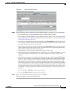
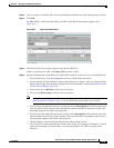
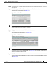
Step 13 After you specify all the PEs, ISC creates the links between PEs based on the Topology that you chose.
Step 14 Click OK.
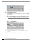
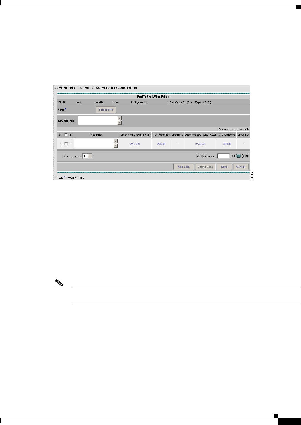
For ERS (EVPL), ATM, and Frame Relay, the End-to-End-Wire Editor window appears. (See
Figure 8-21.)
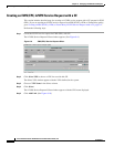
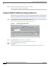
Figure 8-21 End-to-End Wire Editor
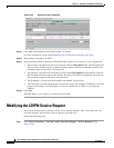
Step 15 The VPN for this service request appears in the Select VPN field.
If there is more than one VPN, click Select VPN to choose a VPN.
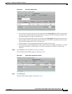
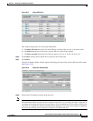
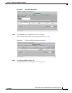
Step 16 Specify remaining items in the End-to-End-Wire Editor window, as necessary for your configuration:
• You can choose any of the blue highlighted values to edit the End-to-End Wire.
• You can edit the AC link attributes to change the default policy settings. After you edit these fields,
the blue link changes from Default to Changed. For more information, see the section
Modifying the
L2VPN Service Request, page 8-20.
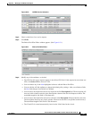
• You can also click Add Link to add an end-to-end wire.
• You can click Delete Link to delete an end-to-end wire.
Note If you are attempting to decommission a service request to which a template has been added, see
Monitoring Service Requests, page 11-10 for information on the proper way to do this.
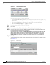
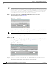
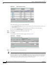
• You can enter a description for the service request in the first Description field. The description will
show up in this window and also in the Description column of the Service Requests window. The
maximum length for this field is 256 characters.
• You can enter a description for each end-to-end wire in the Description field provided for each wire.
The description shows up only in this window. The data in this field is not pushed to the device(s).
The maximum length for this field is 256 characters.
• The ID number is system-generated identification number for the circuit.
• The Circuit ID is created automatically, based on the service. For example, for Ethernet, it is based
on the VLAN number; for Frame Relay, it is based on the DLCI; for ATM, it is based on the
VPI/VCI.