


E-6
Cisco IP Solution Center L2VPN and Carrier Ethernet User Guide, 6.0
OL-21636-01
Appendix E ISC Layer 2 VPN Concepts
L2VPN Service Provisioning
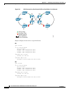
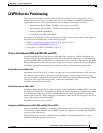
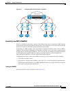
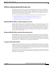
• Single PE scenario—The customer is directly connected to an Ethernet port on the N-PE in
Figure E-2.
Figure E-2 Single PE scenario
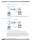
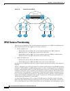
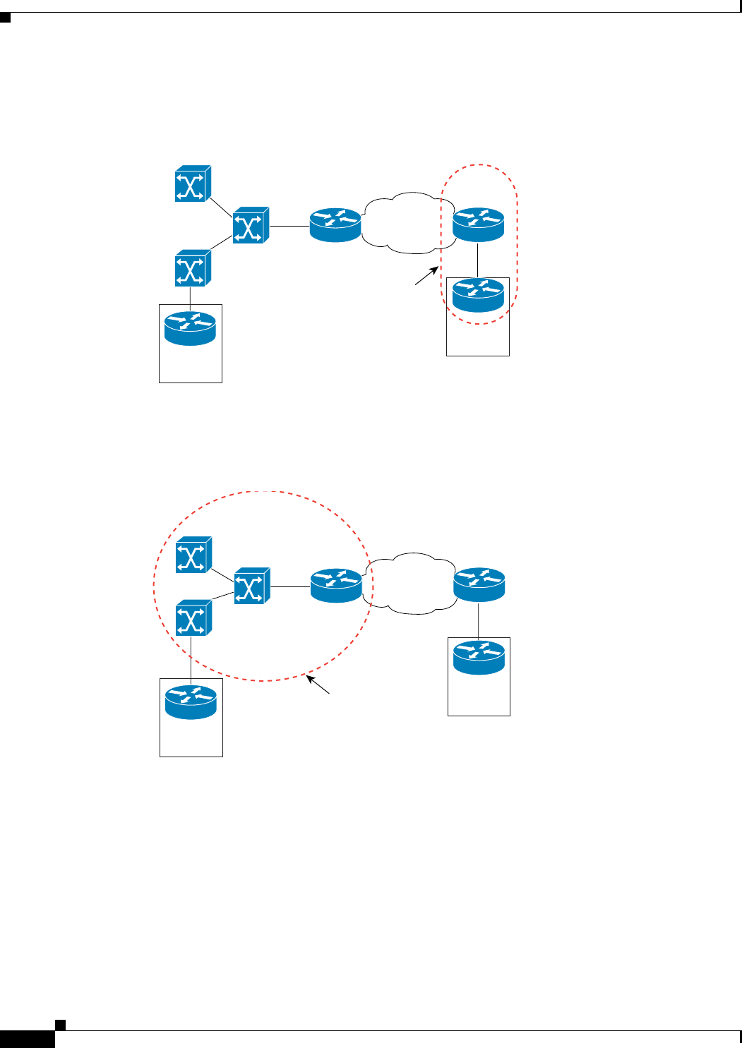
• Distributed PE scenario—The end customer is connected through an Access Domain to the N-PE in
Figure E-3. That is, there is a Layer 2 switching environment in the middle of CE and N-PE.
Figure E-3 Distributed PE Scenario
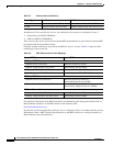
In both cases, a VLAN is assigned in one of the following ways:
• Automatically assigned by ISC from the VLAN pool that is predefined by the user.
• Manually assigned by the user through the GUI or the North Bound Interface (NBI).
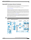
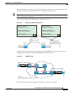
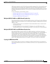
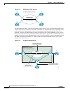
In EoMPLS, ISC creates a point-to-point tunnel and then targets the EoMPLS tunnel to the peer N-PE
router through which the remote site can be reached. The remote N-PE is identified by its loopback
address. In
Figure E-4, N-PE1 and N-PE2 have 10.1.1.1 and 10.2.2.2 as loopback addresses. In
Figure E-4, Site A has been allocated a VLAN-100 and Site B a VLAN-200. You can have different
VLAN IDs at either end of the circuit because the VLANs have local significance only (that is, within
the Ethernet access domain which is delimited by the N-PE).
138356
PE_AGG
U_PE
U_PE
N_PE1
10.1.1.1
N_PE2
10.2.2.2
Site A
CE
Site B
CE
Single PE
scenario
MPLS Core
138357
PE_AGG
N_PE1
10.1.1.1
N_PE2
10.2.2.2
Site A
CE
Site B
CE
Distributed PE
scenario
MPLS Core
Ethernet Services
U_PE
U_PE
U_PE
U_PE