


4-9
Cisco IP Solution Center L2VPN and Carrier Ethernet User Guide, 6.0
OL-21636-01
Chapter 4 Managing a FlexUNI/EVC Ethernet Service Request
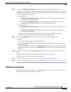
Setting the Service Request Details
• If Configure Bridge Domain is checked, all links will have the same bridge domain ID allocated
from the VLAN pool on the N-PE. All non-FlexUNI links will have the Service Provider VLAN as
the bridge domain ID. On the other hand, if no FlexUNI links are added, the Service Provider VLAN
will be allocated first and this will be used as the bridge domain ID when FlexUNI links are added.
• If Configure Bridge Domain is unchecked, a maximum of two links that terminate on the same N-PE
can be added. (This uses the connect command available in the EVC infrastructure.)
Note See the following comments for details on how ISC autogenerates the connect name.
Because the device only accepts a maximum of 15 characters for the connect name, the connect
name is generated using the following format:
CustomerNameTruncatedToMaxPossibleCharacters_ServiceRequestJobID
For example, if the customer name is NorthAmericanCustomer and the service request job ID is
56345, the autogenerated connect name would be NorthAmer_56345.
The CLI generated would be:
connect NorthAmer_56345 GigabitEthernet7/0/5 11 GigabitEthernet7/0/4 18
In this case, 11 and 18 are service instance IDs.
• If the policy setting for Configure Bridge Domain is non-editable, the option in the service request
will be read-only.
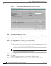
Step 7 Check the Use Split Horizon check box to enable split horizon with bridge domain.
Usage notes:
• The Use Split Horizon attribute is disabled by default.
• The Use Split Horizon attribute can be used only when the Configure Bridge Domain check box is
checked (enabled).
• When Use Split Horizon is enabled, the bridge domain command in the CLI will be generated with
split horizon. When it is disabled, the bridge domain command will be generated without split
horizon.
Step 8 Click the “Click here” link of the Description attribute to enter a description label for the service
request.
A dialogue appears in which you can enter a description.
Step 9 To set up direct connect links, see the section Setting Direct Connect Links, page 4-10.
Step 10 To set up links with L2 access nodes, see the section Setting Links with L2 Access Nodes, page 4-20.
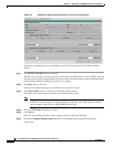
Setting up Links to the N-PE
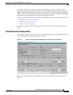
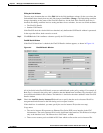
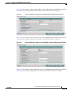
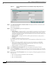
The lower two sections of the EVC Service Request Editor window allow you to set up links to the N-PE.
For direct connect links, the CE is directly connected to the N-PE, with no intermediate L2 access nodes.
For links with L2 access nodes, there are intermediate devices present between the CE and NPE
requiring NPCs to be created in ISC.
The Direct Connect Link section of the window is where you set up links that directly connect to the
N-PE. No NPC are involved. The Links with L2 Access Nodes section is where you set up links with L2
(Ethernet) access nodes. NPCs are involved.