


CHAPTER
10-1
Cisco IP Solution Center L2VPN and Carrier Ethernet User Guide, 6.0
OL-21636-01
10
Managing a VPLS Service Request
This chapter contains the basic steps to provision a VPLS service. It contains the following sections:
• Introducing VPLS Service Requests, page 10-1
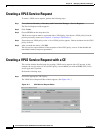
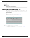
• Creating a VPLS Service Request, page 10-2
• Creating a VPLS Service Request with a CE, page 10-2
• Creating a VPLS Service Request without a CE, page 10-6
• Modifying the VPLS Service Request, page 10-10
• Using the Bridge Domain ID Attribute, page 10-13
• Saving the VPLS Service Request, page 10-14
Introducing VPLS Service Requests
A VPLS service request consists of one or more attachment circuits, connecting various sites in a
multipoint topology. When you create a service request, you enter several parameters, including the
specific interfaces on the CE and PE routers and UNI parameters. You can also integrate a Cisco IP
Solution Center (ISC) template with a service request. You can associate one or more templates to the
CE, PE, or any U-PE in the middle.
To create a service request, a service policy must already be defined, as described in Chapter 9, “Creating
a VPLS Policy.” Based on the predefined VPLS policy, an operator creates a VPLS service request, with
or without modifications to the VPLS policy, and deploys the service. The service request must be the
same service type (ERMS/EVP-LAN or EMS/EP-LAN) as the policy selected. Service creation and
deployment are normally performed by regular network technicians for daily operation of network
provisioning.
The following steps are involved in creating a service request for Layer 2 connectivity between customer
sites:
• Choose a VPLS policy.
• Choose a VPN. For more information, see Defining VPNs, page 2-4.
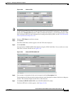
• Add a link.
• Choose a CE or UNI interface.
• Choose a Named Physical Circuit (NPC) if more than one NPC exists from the CE or the UNI
interface.
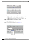
• Edit the link attributes.