


D-9
Cisco IP Solution Center L2VPN and Carrier Ethernet User Guide, 6.0
OL-21636-01
Appendix D Terminating an Access Ring on Two N-PEs
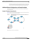
Additional Network Configurations and Sample Configlets
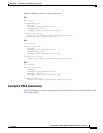
Sample configlets for the devices are provided below.
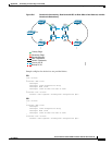
PE1
vlan <S-Vlan>
!
interface <UNI-to-R1>
switchport
switchport trunk encapsulation dot1q
switchport mode trunk
switchport trunk allowed vlan add <S-Vlan>
!
interface vlan <S-Vlan>
xconnect <PE2 loopback> <PrimaryVcId> encapsulation mpls
backup peer <PE3 loopback> <BackupVcId>
PE2
vlan <S-Vlan>
!
interface <UNI-to-R4>
switchport
switchport trunk encapsulation dot1q
switchport mode trunk
switchport trunk allowed vlan add <S-Vlan>
!
interface vlan <S-Vlan>
xconnect <PE1 loopback> <PrimaryVcId> encapsulation mpls
PE3
vlan <S-Vlan>
!
interface <UNI-to-R5>
switchport
switchport trunk encapsulation dot1q
switchport mode trunk
switchport trunk allowed vlan add <S-Vlan>
!
interface vlan <S-Vlan>
xconnect <PE1 loopback> <BackupVcId> encapsulation mpls
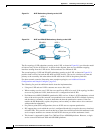
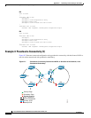
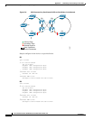
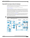
Example 4: VPLS Connectivity
Figure D-8 illustrates a network configuration using VPLS connectivity with dual-homed N-PEs on both
sides of the network.