2-102
Section 2— Control Panel Descriptions
Rear Panel Switches
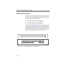
The rear panel includes a number of switches that control
operating modes, such as address, bus enable, delegate enable,
and test mode. These switches are set up during installation, as
described in the Installation section of the Model 2200 Installation
and Service Manual.
Remote Aux Operation
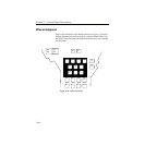
Operation of the Remote Aux Panel is identical to operation of the
local aux panel installed in the switcher control panel.
If the switcher setup identifies a bus pair (that is 2A and 2B) as
video and key, selecting a source on bus 2A will also change 2B.
To split the key selection will require use of the 3-RU panel or two
of the 1-RU or 2-RU panels (one set up for each bus).
More than one Remote Aux Control Panel can attempt to control
a single aux bus. When two or more panels controlling the same
bus have source buttons pressed, the panel with the highest
address will control the source.
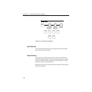
Chop
The chop function switches rapidly between two inputs; this is a
test function and not a creative feature. To start the chop function,
press the first input button then double press the second input
button. to stop the chop button press any input button for that aux
bus on any aux panel. Chop must be enabled on the rear of the
Remote Aux Control Panel.


