


1-10
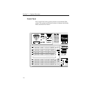
Section 1 — System Overview
Functional Description
General Overview
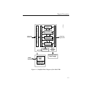
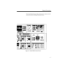
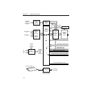
Figure 1-3 shows a simple video flow diagram for the Model 2200.
Video and key signals enter the input modules of the Model 2200,
which consist of component analog and/or component serial
digital formats. The analog signals are converted to digital format,
and all inputs are timed and conditioned.
The digital signals are then passed to the Video and Effects Section
where keying and mixing take place. This section also provides
effect modifications, such as wipes and keyframing, that can be
applied to selected inputs.
In the Output Section, digital video and key signals are routed to
the Serial Digital Output Modules and the optional Analog
Output Module before leaving the Signal Processor.
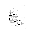
Video Processing
Input video and key signal selections are made by the Crosspoint
Matrix under control of the system Controller, according to
operator assignments entered via the Control Panel.
In addition to primary (external) video, secondary (internal)
sources such as Masks, M/E re-entry video, and optional Effects
Send are available as inputs to the crosspoint matrix.
Any suitable component digital signal from the Crosspoint matrix
may feed the Chromatte™ Chroma Keyer Module option. Analog
Component signals may also be used as Chroma Key sources.
Keyers in each Mix/Effects bank provide outputs to the Mixer
Interface crosspoints. These outputs may be sent outside the
switcher for external processing, or may be routed to the M/E
mixers and wipe generators. The Effects Send outputs can be
directed to the Framestore option for image capture.