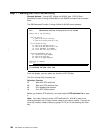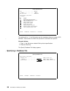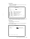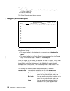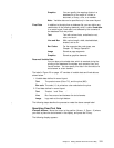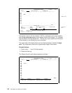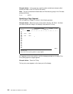
Design Record Layout Columns: 1- 74
Control . . PFD definition . . . . . PRODUCTLBL
ᑍ...+....1....+....2....+....3....+....4....+....5....+....6....+.... ──┐
1
2
3 %T1
4
5 ├─ Image area
6
7
8
9
1
11
12
__________________________________________________________________More... ──┘
Define Text ──┐
Mark . . . . . . : ᑍT1 Measurement method . . . . : Row/Column Key entry
Position . . . . . Across 3 Down 3 ├─ area
Text data . . . . Product :
──┘
F3=Exit F4=Detail F6=Change measurement method
F12=Cancel F24=More keys
The element mark for the text element (%T001) is displayed at the cursor position,
and the key entry area appears at the bottom portion of the display. A % indicates
that the element is being worked with. The key entry area contains the information
of the element you are specifying, such as position.
The upper area of the display where you can place elements is called the image
area. The image area shows you an approximate image of the printout.
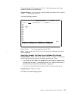
Example Actions:
1. Type Product : in the
Text data
prompt.
2. Press the Enter key.
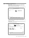
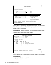
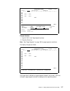
The Design Record Layout display appears as follows.
Design Record Layout Columns: 1- 74
Control . . PFD definition . . . . . PRODUCTLBL
ᑍ...+....1....+....2....+....3....+....4....+....5....+....6....+....7....
1
2
3 ᑍT1 t :
4
5
6
7
8
9
1
11
12
13
14
15
16
17
More...
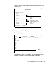
F3=Exit F6=Text F9=Line F1=Box
F11=Bar code F21=Element edit F22=Block edit F24=More keys
112 AFP Utilities for AS/400 User’s Guide


