


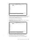
Example Action:
Press the Enter key.
The line is defined.
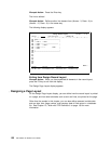
Example Action:
Define another line element from (Across : 3, Down : 6) to
(Across : 15, Down : 6) in the same way.
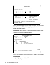
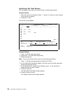
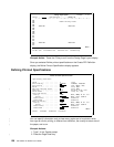
The following display appears.
Design Record Layout Columns: 1- 74
Control . . PFD definition . . . . . PRODUCTLBL
ᑍ...+....1....+....2....+....3....+....4....+....5....+....6....+....7....
1 ᑍB7 ----------------------------+
2 : :
3 : ᑍT1 t : ᑍT3 :
4 : ᑍL8 ------------------------- :
5 : ᑍT2 : ᑍT4 . :
6 : ᑍL9 ------- ᑍS5 :
7 : ᑍC6 :
8 : :
9 +---------------------------------+
1
11
12
13
14
15
16
17
More...
F3=Exit F6=Text F9=Line F1=Box
F11=Bar code F21=Element edit F22=Block edit F24=More keys
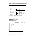
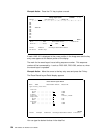
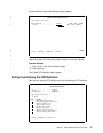
Exiting from Design Record Layout
Example Action:
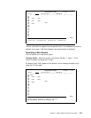
When you have specified all elements in the record layout,
press the F3 key to exit from this display.
The Design Page Layout display appears.
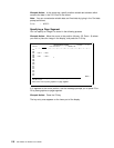
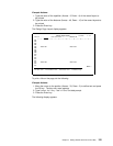
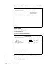
| Designing a Page Layout
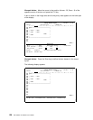
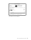
On the Design Page Layout display, you can define how the record layout is printed
on a page, and how other elements such as text and lines, are printed on the page.
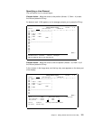
Other than the sample in this chapter, you can also define reserved variable data
such as date, time, page number, and summary data of field values in a database
file. See Chapter 10, “Work with PFD Definitions” on page 139 for more
information.
122 AFP Utilities for AS/400 User’s Guide