


4−16
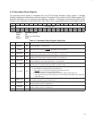
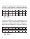
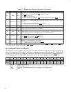
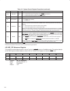
Table 4−7. Bridge Control Register Description (Continued)
BIT
SIGNAL TYPE FUNCTION
6 † CRST RW
CardBus reset. When this bit is set, the CRST signal is asserted on the CardBus interface. The CRST
signal can also be asserted by passing a PRST assertion to CardBus.
0 = CRST
is deasserted.
1 = CRST
is asserted (default).
This bit is not cleared by the assertion of PRST
. It is only cleared by the assertion of GRST.
5 MABTMODE RW
Master abort mode. This bit controls how the PCI7x21/PCI7x11 controller responds to a master abort when
the PCI7x21/PCI7x11 controller is an initiator on the CardBus interface. This bit is common between each
socket.
0 = Master aborts not reported (default).
1 = Signal target abort on PCI and signal SERR
, if enabled.
4 RSVD R This bit returns 0 when read.
3 VGAEN RW
VGA enable. This bit affects how the PCI7x21/PCI7x11 controller responds to VGA addresses. When this
bit is set, accesses to VGA addresses are forwarded.
2 ISAEN RW
ISA mode enable. This bit affects how the PCI7x21/PCI7x11 controller passes I/O cycles within the
64-Kbyte ISA range. This bit is not common between sockets. When this bit is set, the PCI7x21/PCI7x11
controller does not forward the last 768 bytes of each 1K I/O range to CardBus.
1 CSERREN RW
CSERR enable. This bit controls the response of the PCI7x21/PCI7x11 controller to CSERR signals on
the CardBus bus. This bit is separate for each socket.
0 = CSERR is not forwarded to PCI SERR (default)
1 = CSERR
is forwarded to PCI SERR.
0 CPERREN RW
CardBus parity error response enable. This bit controls the response of the PCI7x21/PCI7x11 to CardBus
parity errors. This bit is separate for each socket.
0 = CardBus parity errors are ignored (default).
1 = CardBus parity errors are reported using CPERR
.
†
One or more bits in this register are PME context bits and can be cleared only by the assertion of GRST
when PME is enabled. If PME is not
enabled, then this bit is cleared by the assertion of PRST
or GRST.
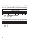
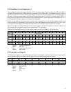
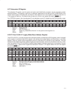
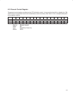
4.26 Subsystem Vendor ID Register
The subsystem vendor ID register, used for system and option card identification purposes, may be required for
certain operating systems. This register is read-only or read/write, depending on the setting of bit 5 (SUBSYSRW)
in the system control register (PCI offset 80h, See Section 4.29). When bit 5 is 0, this register is read/write; when bit 5
is 1, this register is read-only. The default mode is read-only. All bits in this register are reset by GRST
only.
Bit 15 14 13 12 11 10 9 8 7 6 5 4 3 2 1 0
Name Subsystem vendor ID
Type R R R R R R R R R R R R R R R R
Default 0 0 0 0 0 0 0 0 0 0 0 0 0 0 0 0
Register: Subsystem vendor ID
Offset: 40h (Functions 0, 1)
Type: Read-only, (Read/Write when bit 5 in the system control register is 0)
Default: 0000h