


7−20
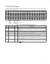
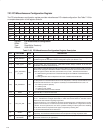
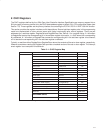
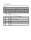
Table 7−23. GPIO Control Register Description (Continued)
BIT SIGNAL TYPE FUNCTION
12 GPIO_ENB1 R/W
GPIO1 enable control. When bit 15 (DISABLE_LPS) is set to 1, this bit controls the output enable for
GPIO1.
0 = High-impedance output (default)
1 = Output is enabled
11−9 RSVD R Reserved. Bits 11−9 return 0s when read.
8 GPIO_DATA1 R/W
GPIO1 data. When bit 15 (DISABLE_LPS) is set to 1 and GPIO1 output is enabled, the value written to
this bit represents the logical data driven to the GPIO1 terminal.
7 DISABLE_BMC R/W
Disable bus manager contender (BMC). This bit configures this terminal as bus manager contender or
GPIO0.
0 = BMC (default)
1 = GPIO0
6 RSVD R Reserved. Bit 6 returns 0 when read.
5 GPIO_INV0 R/W
GPIO0 polarity invert. When bit 7 (DISABLE_BMC) is set to 1, this bit controls the input/output polarity
control for GPIO0.
0 = Noninverted (default)
1 = Inverted
4 GPIO_ENB0 R/W
GPIO0 enable control. When bit 7 (DISABLE_BMC) is set to 1, this bit controls the output enable for
GPIO0.
0 = High-impedance output (default)
1 = Output is enabled
3−1 RSVD R Reserved. Bits 3−1 return 0s when read.
0 GPIO_DATA0 R/W
GPIO0 data. When bit 7 (DISABLE_BMC) is set to 1 and GPIO0 output is enabled, the value written to
this bit represents the logical data driven to the GPIO0 terminal.