


3−27
The Texas Instruments PCI7x21/PCI7x11 controller addresses these D3 wake-up issues in the following manner:
• Two resets are provided to handle preservation of PME
context bits:
− Global reset (GRST
) is used only on the initial boot up of the system after power up. It places the
PCI7x21/PCI7x11 controller in its default state and requires BIOS to configure the controller before
becoming fully functional.
− PCI reset (PRST
) has dual functionality based on whether PME is enabled or not. If PME is enabled,
then PME
context is preserved. If PME is not enabled, then PRST acts the same as a normal PCI reset.
Please see the master list of PME
context bits in Section 3.8.12.
• Power source in D3
cold
if wake-up support is required from this state. Since V
CC
is removed in D3
cold
, an
auxiliary power source must be supplied to the PCI7x21/PCI7x11 V
CC
terminals. Consult the PCI14xx
Implementation Guide for D3 Wake-Up or the PCI Power Management Interface Specification for PCI to
CardBus Bridges for further information.
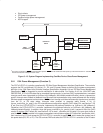
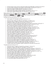
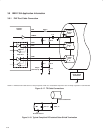
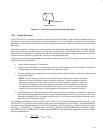
3.8.11 ACPI Support
The Advanced Configuration and Power Interface (ACPI) Specification provides a mechanism that allows unique
pieces of hardware to be described to the ACPI driver. The PCI7x21/PCI7x11 controller offers a generic interface that
is compliant with ACPI design rules.
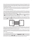
Two doublewords of general-purpose ACPI programming bits reside in PCI7x21/PCI7x11 PCI configuration space
at offset 88h. The programming model is broken into status and control functions. In compliance with ACPI, the top
level event status and enable bits reside in the general-purpose event status register (PCI offset 88h, see
Section 4.32) and general-purpose event enable register (PCI offset 89h, see Section 4.33). The status and enable
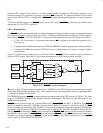
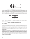
bits are implemented as defined by ACPI and illustrated in Figure 3−16.
Event Output
Event Input
Enable Bit
Status Bit
Figure 3−16. Block Diagram of a Status/Enable Cell
The status and enable bits generate an event that allows the ACPI driver to call a control method associated with the
pending status bit. The control method can then control the hardware by manipulating the hardware control bits or
by investigating child status bits and calling their respective control methods. A hierarchical implementation would
be somewhat limiting, however, as upstream devices would have to remain in some level of power state to report
events.
For more information of ACPI, see the Advanced Configuration and Power Interface (ACPI) Specification.
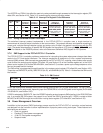
3.8.12 Master List of PME Context Bits and Global Reset-Only Bits
PME context bit means that the bit is cleared only by the assertion of GRST when the PME enable bit, bit 8 of the
power management control/status register (PCI offset A4h, see Section 4.44) is set. If PME
is not enabled, then these
bits are cleared when either PRST
or GRST is asserted.
The PME
context bits (functions 0 and 1) are:
• Bridge control register (PCI offset 3Eh, see Section 4.25): bit 6
• System control register (PCI offset 80h, see Section 4.29): bits 10−8
• Power management control/status register (PCI offset A4h, see Section 4.44): bit 15
• ExCA power control register (ExCA 802h/842h, see Section 5.3): bits 7, 5 (82365SL mode only), 4, 3, 1,
0
• ExCA interrupt and general control (ExCA 803h/843h, see Section 5.4): bits 6, 5
• ExCA card status-change register (ExCA 804h/844h, see Section 5.5): bits 3−0