


3−24
places the PCI outputs of the controller in a high-impedance state and gates the PCLK signal internally to the
controller unless a PCI transaction is currently in process (GNT
is asserted). It is important that the PCI bus not be
parked on the PCI7x21/PCI7x11 controller when SUSPEND
is asserted because the outputs are in a high-impedance
state.
The GPIOs, MFUNC signals, and RI_OUT
signal are all active during SUSPEND, unless they are disabled in the
appropriate PCI7x21/PCI7x11 registers.
3.8.8 Ring Indicate
The RI_OUT output is an important feature in power management, allowing a system to go into a suspended mode
and wake-up on modem rings and other card events. TI-designed flexibility permits this signal to fit wide platform
requirements. RI_OUT
on the PCI7x21/PCI7x11 controller can be asserted under any of the following conditions:
• A 16-bit PC Card modem in a powered socket asserts RI
to indicate to the system the presence of an
incoming call.
• A powered down CardBus card asserts CSTSCHG (CBWAKE) requesting system and interface wake-up.
• A powered CardBus card asserts CSTSCHG from the insertion/removal of cards or change in battery
voltage levels.
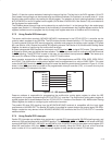
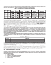
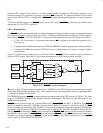
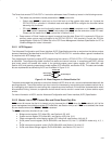
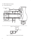
Figure 3−15 shows various enable bits for the PCI7x21/PCI7x11 RI_OUT
function; however, it does not show the
masking of CSC events. See Table 3−10 for a detailed description of CSC interrupt masks and flags.
Card
I/F
PC Card
Socket A
CSC
CSTSMASK
RIENB
RI_OUT
RI_OUT Function
RINGEN
CDRESUME
CSC
RI
PC Card
Socket B
Figure 3−15. RI_OUT Functional Diagram
RI from the 16-bit PC Card interface is masked by bit 7 (RINGEN) in the ExCA interrupt and general control register
(ExCA offset 03h/43h/803h, see Section 5.4). This is programmed on a per-socket basis and is only applicable when
a 16-bit card is powered in the socket.
The CBWAKE signaling to RI_OUT
is enabled through the same mask as the CSC event for CSTSCHG. The mask
bit (bit 0, CSTSMASK) is programmed through the socket mask register (CB offset 04h, see Section 6.2) in the
CardBus socket registers.
RI_OUT
can be routed through any of three different pins, RI_OUT/PME, MFUNC2, or MFUNC4. The RI_OUT
function is enabled by setting bit 7 (RIENB) in the card control register (PCI offset 91h, see Section 4.38). The PME
function is enabled by setting bit 8 (PME_ENABLE) in the power-management control/status register (PCI offset A4h,
see Section 4.44). When bit 0 (RIMUX) in the system control register (PCI offset 80h, see Section 4.29) is set to 0,
both the RI_OUT
function and the PME function are routed to the RI_OUT/PME terminal. If both functions are enabled
and RIMUX is set to 0, then the RI_OUT
/PME terminal becomes RI_OUT only and PME assertions are never seen.
Therefore, in a system using both the RI_OUT
function and the PME function, RIMUX must be set to 1 and RI_OUT
must be routed to either MFUNC2 or MFUNC4.