


3−19
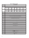
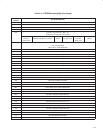
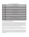
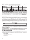
Table 3−10 lists the various methods of clearing the interrupt flag bits. The flag bits in the ExCA registers (16-bit PC
Card-related interrupt flags) can be cleared using two different methods. One method is an explicit write of 1 to the
flag bit to clear and the other is by reading the flag bit register. The selection of flag bit clearing methods is made by
bit 2 (IFCMODE) in the ExCA global control register (ExCA offset 1Eh/5Eh/81Eh, see Section 5.20), and defaults to
the flag-cleared-on-read method.
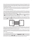
The CardBus-related interrupt flags can be cleared by an explicit write of 1 to the interrupt flag in the socket event
register (see Section 6.1). Although some of the functionality is shared between the CardBus registers and the ExCA
registers, software must not program the chip through both register sets when a CardBus card is functioning.
3.7.3 Using Parallel IRQ Interrupts
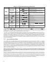
The seven multifunction terminals, MFUNC6−MFUNC0, implemented in the PCI7x21/PCI7x11 controller can be
routed to obtain a subset of the ISA IRQs. The IRQ choices provide ultimate flexibility in PC Card host interruptions.
To use the parallel ISA-type IRQ interrupt signaling, software must program the device control register (PCI offset
92h, see Section 4.39), to select the parallel IRQ signaling scheme. See Section 4.36, Multifunction Routing Status
Register, for details on configuring the multifunction terminals.
A system using parallel IRQs requires (at a minimum) one PCI terminal, INTA
, to signal CSC events. This requirement
is dictated by certain card and socket-services software. The INTA
requirement calls for routing the MFUNC0 terminal
for INTA
signaling. The INTRTIE bit is used, in this case, to route socket interrupt events to INTA. This leaves (at a
maximum) six different IRQs to support legacy 16-bit PC Card functions.
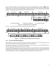
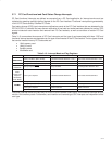
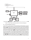
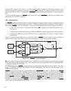
As an example, suppose the six IRQs used by legacy PC Card applications are IRQ3, IRQ4, IRQ5, IRQ9, IRQ10,
and IRQ15. The multifunction routing status register must be programmed to a value of 0A9F 5432h. This value
routes the MFUNC0 terminal to INTA
signaling and routes the remaining terminals as illustrated in Figure 3−12. Not
shown is that INTA
must also be routed to the programmable interrupt controller (PIC), or to some circuitry that
provides parallel PCI interrupts to the host.
PIC
MFUNC1
MFUNC2
MFUNC3
MFUNC4
MFUNC5
MFUNC6
IRQ3
IRQ4
IRQ5
IRQ15
IRQ9
IRQ10
PCI7x21/PCI7x11
Figure 3−12. IRQ Implementation
Power-on software is responsible for programming the multifunction routing status register to reflect the IRQ
configuration of a system implementing the PCI7x21/PCI7x11 controller. The multifunction routing status register is
a global register that is shared between the four PCI7x21/PCI7x11 functions. See Section 4.36, Multifunction Routing
Status Register,
for details on configuring the multifunction terminals.
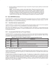
The parallel ISA-type IRQ signaling from the MFUNC6−MFUNC0 terminals is compatible with the input signal
requirements of the 8259 PIC. The parallel IRQ option is provided for system designs that require legacy ISA IRQs.
Design constraints may demand more MFUNC6−MFUNC0 IRQ terminals than the PCI7x21/PCI7x11 controller
makes available.
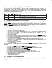
3.7.4 Using Parallel PCI Interrupts
Parallel PCI interrupts are available when exclusively in parallel PCI interrupt/parallel ISA IRQ signaling mode, and
when only IRQs are serialized with the IRQSER protocol. The INTA
, INTB, INTC, and INTD can be routed to MFUNC
terminals (MFUNC0, MFUNC1, MFUNC2, and MFUNC4). If bit 29 (INTRTIE) is set in the system control register (PCI
offset 80h, see Section 4.29), then INTA
and INTB are tied internally. When the TIEALL bit is set, all four functions
return a value of 01h on reads from the interrupt pin register for both parallel and serial PCI interrupts.