


4−9
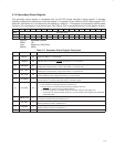
4.14 Secondary Status Register
The secondary status register is compatible with the PCI-PCI bridge secondary status register. It indicates
CardBus-related device information to the host system. This register is very similar to the PCI status register (PCI
offset 06h, see Section 4.5), and status bits are cleared by a writing a 1. This register is not shared by the two socket
functions, but is accessed on a per-socket basis. See Table 4−5 for a complete description of the register contents.
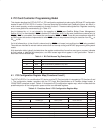
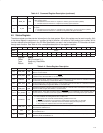
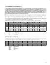
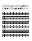
Bit 15 14 13 12 11 10 9 8 7 6 5 4 3 2 1 0
Name Secondary status
Type RC RC RC RC RC R R RC R R R R R R R R
Default 0 0 0 0 0 0 1 0 0 0 0 0 0 0 0 0
Register: Secondary status
Offset: 16h
Type: Read-only, Read/Clear
Default: 0200h
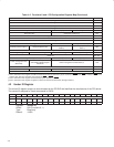
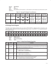
Table 4−5. Secondary Status Register Description
BIT SIGNAL TYPE FUNCTION
15 ‡ CBPARITY RC
Detected parity error. This bit is set when a CardBus parity error is detected, either an address or data
parity error. Write a 1 to clear this bit.
14 ‡ CBSERR RC
Signaled system error. This bit is set when CSERR is signaled by a CardBus card. The PCI7x21/PCI7x11
controller does not assert the CSERR
signal. Write a 1 to clear this bit.
13 ‡ CBMABORT RC
Received master abort. This bit is set when a cycle initiated by the PCI7x21/PCI7x11 controller on the
CardBus bus is terminated by a master abort. Write a 1 to clear this bit.
12 ‡ REC_CBTA RC
Received target abort. This bit is set when a cycle initiated by the PCI7x21/PCI7x11 controller on the
CardBus bus is terminated by a target abort. Write a 1 to clear this bit.
11 ‡ SIG_CBTA RC
Signaled target abort. This bit is set by the PCI7x21/PCI7x11 controller when it terminates a transaction
on the CardBus bus with a target abort. Write a 1 to clear this bit.
10−9 CB_SPEED R
CDEVSEL timing. These bits encode the timing of CDEVSEL and are hardwired to 01b indicating that the
PCI7x21/PCI7x11 controller asserts this signal at a medium speed.
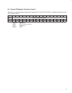
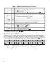
8 ‡ CB_DPAR RC
CardBus data parity error detected. Write a 1 to clear this bit.
0 = The conditions for setting this bit have not been met.
1 = A data parity error occurred and the following conditions were met:
a. CPERR
was asserted on the CardBus interface.
b. The PCI7x21/PCI7x11 controller was the bus master during the data parity error.
c. The parity error response enable bit (bit 0) is set in the bridge control register (PCI offset 3Eh,
see Section 4.25).
7 CBFBB_CAP R
Fast back-to-back capable. The PCI7x21/PCI7x11 controller cannot accept fast back-to-back
transactions; therefore, this bit is hardwired to 0.
6 CB_UDF R
User-definable feature support. The PCI7x21/PCI7x11 controller does not support user-definable
features; therefore, this bit is hardwired to 0.
5 CB66MHZ R
66-MHz capable. The PCI7x21/PCI7x11 CardBus interface operates at a maximum CCLK frequency of
33 MHz; therefore, this bit is hardwired to 0.
4−0 RSVD R These bits return 0s when read.
‡
This bit is cleared only by the assertion of GRST
.