


13−16
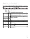
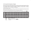
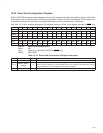
Table 13−15. Smart Card Configuration 1 Register Description
BIT FIELD NAME TYPE DESCRIPTION
31−28 SCRTCH_PAD RW Scratch pad
27 CLASS_B_SKT3 R Socket 3 Class B Smart Card support. Since socket 3 is not implemented in the controller, this
bit is a read-only 0.
26 CLASS_B_SKT2 RW Socket 2 Class B Smart Card support. Since socket 2 is not implemented in the controller, this
bit is a read-only 0.
25 CLASS_B_SKT1 RW Socket 1 Class B Smart Card support. When this bit is set to 1, socket 1 supports Class B Smart
Cards.
24 CLASS_B_SKT0 RW Socket 0 Class B Smart Card support. When this bit is set to 1, socket 0 supports Class B Smart
Cards.
23 CLASS_A_SKT3 R Socket 3 Class A Smart Card support. Since socket 3 is not implemented in the controller, this
bit is a read-only 0.
22 CLASS_A_SKT2 RW Socket 2 Class A Smart Card support. Since socket 2 is not implemented in the controller, this
bit is a read-only 0.
21 CLASS_A_SKT1 RW Socket 1 Class A Smart Card support. When this bit is set to 1, socket 1 supports Class A Smart
Cards.
20 CLASS_A_SKT0 RW Socket 0 Class A Smart Card support. When this bit is set to 1, socket 0 supports Class A Smart
Cards.
19 EMVIF_EN_SKT3 R Socket 3 EMV interface enable. Since socket 3 is not implemented in the controller, this bit is
a read-only 0.
18 EMVIF_EN_SKT2 RW Socket 2 EMV interface enable. Since socket 2 is not implemented in the controller, this bit is
a read-only 0.
17 EMVIF_EN_SKT1 RW Socket 1 EMV interface enable. When this bit is set to 1, the internal EVM interface for socket
1 is enabled.
16 EMVIF_EN_SKT0 RW Socket 0 EMV interface enable. When this bit is set to 1, the internal EVM interface for socket
0 is enabled.
15 GPIO_EN_SKT3 R Socket 3 GPIO enable. Since socket 3 is not implemented in the controller, this bit is a read-only
0.
14 GPIO_EN_SKT2 RW Socket 2 GPIO enable. Since socket 2 is not implemented in the controller, this bit is a read-only
0.
13 GPIO_EN_SKT1 RW Socket 1 GPIO enable. When this bit is set to 1, the SC_GPIOs for socket 1 are enabled.
12 GPIO_EN_SKT0 RW Socket 0 GPIO enable. When this bit is set to 1, the SC_GPIOs for socket 0 are enabled.
11 PCMCIA_MODE_SKT3 R Socket 3 PCMCIA mode. Since socket 3 is not implemented in the controller, this bit is a
read-only 0.
10 PCMCIA_MODE_SKT2 R Socket 2 PCMCIA mode. Since socket 2 is not implemented in the controller, this bit is a
read-only 0.
9 PCMCIA_MODE_SKT1 R Socket 1 PCMCIA mode. Since socket 1 is implemented as a dedicated socket in the controller,
this bit returns 1 when read.
8 PCMCIA_MODE_SKT0 R Socket 0 PCMCIA mode. Since socket 0 is implemented as a dedicated socket in the controller,
this bit returns 1 when read.
7 PME_SUPPORT_SKT3 R Socket 3 PME support. Since socket 3 is not implemented in the controller, this bit is a read-only
0.
6 PME_SUPPORT_SKT2 RW Socket 2 PME support. Since socket 2 is not implemented in the controller, this bit is a read-only
0.
5 PME_SUPPORT_SKT1 RW Socket 1 PME support. When this bit is set to 1, socket 1 card insertions cause a PME event.
4 PME_SUPPORT_SKT0 RW Socket 0 PME support. When this bit is set to 1, socket 0 card insertions cause a PME event.
3 SKT3_EN R Socket 3 enable. Since socket 3 is not implemented in the controller, this bit is a read-only 0.
2 SKT2_EN RW Socket 2 enable. Since socket 2 is not implemented in the controller, this bit is a read-only 0.
1 SKT1_EN RW Socket 1 enable. When this bit is set to 1, socket 1 is enabled.
0 SKT0_EN RW Socket 0 enable. When this bit is set to 1, socket 0 is enabled.