


4−19
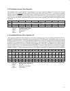
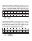
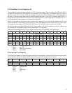
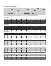
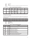
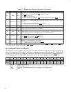
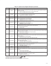
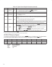
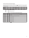
Table 4−8. System Control Register Description (continued)
BIT SIGNAL TYPE FUNCTION
22 ‡ CBRSVD RW
CardBus reserved terminals signaling. When this bit is set, the RSVD CardBus terminals are driven
low when a CardBus card has been inserted. When this bit is low, these signals are placed in a
high-impedance state.
0 = Place the CardBus RSVD terminals in a high-impedance state.
1 = Drive the CardBus RSVD terminals low (default).
21 ‡ VCCPROT RW
V
CC
protection enable. This bit is socket dependent.
0 = V
CC
protection is enabled for 16-bit cards (default).
1 = V
CC
protection is disabled for 16-bit cards.
20−16 ‡ RSVD RW These bits are reserved. Do not change the value of these bits.
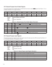
15 ठMRBURSTDN RW
Memory read burst enable downstream. When this bit is set, the PCI7x21/PCI7x11 controller allows
memory read transactions to burst downstream.
0 = MRBURSTDN downstream is disabled.
1 = MRBURSTDN downstream is enabled (default).
14 ठMRBURSTUP RW
Memory read burst enable upstream. When this bit is set, the PCI7x21/PCI7x11 controller allows
memory read transactions to burst upstream.
0 = MRBURSTUP upstream is disabled (default).
1 = MRBURSTUP upstream is enabled.
13 ‡ SOCACTIVE R
Socket activity status. When set, this bit indicates access has been performed to or from a PC Card.
Reading this bit causes it to be cleared. This bit is socket dependent.
0 = No socket activity (default)
1 = Socket activity
12 RSVD R Reserved. This bit returns 1 when read.
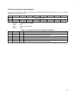
11 ‡ PWRSTREAM R
Power-stream-in-progress status bit. When set, this bit indicates that a power stream to the power
switch is in progress and a powering change has been requested. When this bit is cleared, it indicates
that the power stream is complete.
0 = Power stream is complete, delay has expired (default).
1 = Power stream is in progress.
10 † DELAYUP R
Power-up delay-in-progress status bit. When set, this bit indicates that a power-up stream has been
sent to the power switch, and proper power may not yet be stable. This bit is cleared when the power-up
delay has expired.
0 = Power-up delay has expired (default).
1 = Power-up stream sent to switch. Power might not be stable.
9 † DELAYDOWN R
Power-down delay-in-progress status bit. When set, this bit indicates that a power-down stream has
been sent to the power switch, and proper power may not yet be stable. This bit is cleared when the
power-down delay has expired.
0 = Power-down delay has expired (default).
1 = Power-down stream sent to switch. Power might not be stable.
8 † INTERROGATE R
Interrogation in progress. When set, this bit indicates an interrogation is in progress, and clears when
the interrogation completes. This bit is socket-dependent.
0 = Interrogation not in progress (default)
1 = Interrogation in progress
7 RSVD R Reserved. This bit returns 0 when read.
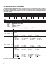
6 ठPWRSAVINGS RW
Power savings mode enable. When this bit is set, the PCI7x21/PCI7x11 controller consumes less
power with no performance loss. This bit is shared between the two PCI7x21/PCI7x11 CardBus
functions.
0 = Power savings mode disabled
1 = Power savings mode enabled (default)
5 ठSUBSYSRW RW
Subsystem ID and subsystem vendor ID, ExCA ID and revision register read/write enable. This bit also
controls read/write for the function 3 subsystem ID register.
0 = Registers are read/write.
1 = Registers are read-only (default).
†
One or more bits in this register are PME context bits and can be cleared only by the assertion of GRST
when PME is enabled. If PME is not
enabled, then this bit is cleared by the assertion of PRST
or GRST.
‡
These bits are cleared only by the assertion of GRST
.
§
These bits are global in nature and must be accessed only through function 0.