


5−6
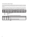
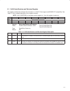
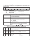
5.2 ExCA Interface Status Register
This register provides information on current status of the PC Card interface. An X in the default bit values indicates
that the value of the bit after reset depends on the state of the PC Card interface. See Table 5−3 for a complete
description of the register contents.
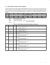
Bit 7 6 5 4 3 2 1 0
Name ExCA interface status
Type R R R R R R R R
Default 0 0 X X X X X X
Register: ExCA interface status
Offset: CardBus Socket Address + 801h: Card A ExCA Offset 01h
Card B ExCA Offset 41h
Type: Read-only
Default: 00XX XXXXb
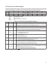
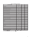
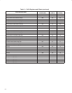
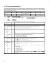
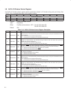
Table 5−3. ExCA Interface Status Register Description
BIT SIGNAL TYPE FUNCTION
7 RSVD R This bit returns 0 when read. A write has no effect.
6 CARDPWR R
CARDPWR. Card power. This bit indicates the current power status of the PC Card socket. This bit reflects
how the ExCA power control register has been programmed. The bit is encoded as:
0 = V
CC
and V
PP
to the socket are turned off (default).
1 = V
CC
and V
PP
to the socket are turned on.
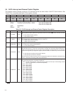
5 READY R
This bit indicates the current status of the READY signal at the PC Card interface.
0 = PC Card is not ready for a data transfer.
1 = PC Card is ready for a data transfer.
4 CARDWP R
Card write protect. This bit indicates the current status of the WP signal at the PC Card interface. This signal
reports to the PCI7x21/PCI7x11 controller whether or not the memory card is write protected. Further, write
protection for an entire PCI7x21/PCI7x11 16-bit memory window is available by setting the appropriate bit
in the ExCA memory window offset-address high-byte register.
0 = WP signal is 0. PC Card is R/W.
1 = WP signal is 1. PC Card is read-only.
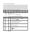
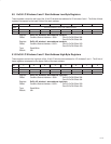
3 CDETECT2 R
Card detect 2. This bit indicates the status of the CD2 signal at the PC Card interface. Software can use
this and CDETECT1 to determine if a PC Card is fully seated in the socket.
0 = CD2
signal is 1. No PC Card inserted.
1 = CD2
signal is 0. PC Card at least partially inserted.
2 CDETECT1 R
Card detect 1. This bit indicates the status of the CD1 signal at the PC Card interface. Software can use
this and CDETECT2 to determine if a PC Card is fully seated in the socket.
0 = CD1
signal is 1. No PC Card inserted.
1 = CD1
signal is 0. PC Card at least partially inserted.
1−0 BVDSTAT R
Battery voltage detect. When a 16-bit memory card is inserted, the field indicates the status of the battery
voltage detect signals (BVD1, BVD2) at the PC Card interface, where bit 0 reflects the BVD1 status, and
bit 1 reflects BVD2.
00 = Battery is dead.
01 = Battery is dead.
10 = Battery is low; warning.
11 = Battery is good.
When a 16-bit I/O card is inserted, this field indicates the status of the SPKR
(bit 1) signal and the STSCHG
(bit 0) at the PC Card interface. In this case, the two bits in this field directly reflect the current state of these
card outputs.