


8−9
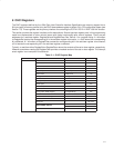
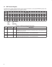
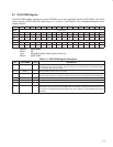
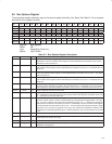
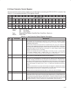
8.9 Bus Options Register
The bus options register externally maps to the second quadlet of the Bus_Info_Block. See Table 8−7 for a complete
description of the register contents.
Bit 31 30 29 28 27 26 25 24 23 22 21 20 19 18 17 16
Name Bus options
Type RW RW RW RW RW R R R RW RW RW RW RW RW RW RW
Default X X X X 0 0 0 0 X X X X X X X X
Bit 15 14 13 12 11 10 9 8 7 6 5 4 3 2 1 0
Name Bus options
Type RW RW RW RW R R R R RW RW R R R R R R
Default 1 0 1 0 0 0 0 0 X X 0 0 0 0 1 0
Register: Bus options
Offset: 20h
Type: Read/Write, Read-only
Default: X0XX A0X2h
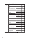
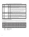
Table 8−7. Bus Options Register Description
BIT FIELD NAME TYPE DESCRIPTION
31 irmc RW Isochronous resource-manager capable. IEEE 1394 bus-management field. Must be valid when bit 17
(linkEnable) in the host controller control register at OHCI offset 50h/54h (see Section 8.16) is set to 1.
The default value for this bit is 0.
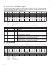
30 cmc RW Cycle master capable. IEEE 1394 bus-management field. Must be valid when bit 17 (linkEnable) in the
host controller control register at OHCI offset 50h/54h (see Section 8.16) is set to 1. The default value for
this bit is 0.
29 isc RW Isochronous support capable. IEEE 1394 bus-management field. Must be valid when bit 17 (linkEnable)
in the host controller control register at OHCI offset 50h/54h (see Section 8.16) is set to 1. The default
value for this bit is 0.
28 bmc RW Bus manager capable. IEEE 1394 bus-management field. Must be valid when bit 17 (linkEnable) in the
host controller control register at OHCI offset 50h/54h (see Section 8.16) is set to 1. The default value for
this bit is 0.
27 pmc RW Power-management capable. IEEE 1394 bus-management field. When bit 27 is set to 1, this indicates that
the node is power-management capable. Must be valid when bit 17 (linkEnable) in the host controller
control register at OHCI offset 50h/54h (see Section 8.16) is set to 1. The default value for this bit is 0.
26−24 RSVD R Reserved. Bits 26−24 return 0s when read.
23−16 cyc_clk_acc RW Cycle master clock accuracy, in parts per million. IEEE 1394 bus-management field. Must be valid when
bit 17 (linkEnable) in the host controller control register at OHCI offset 50h/54h (see Section 8.16) is set
to 1. The default value for this field is 00h.
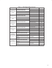
15−12 ‡ max_rec RW Maximum request. IEEE 1394 bus-management field. Hardware initializes this field to indicate the
maximum number of bytes in a block request packet that is supported by the implementation. This value,
max_rec_bytes, must be 512 or greater, and is calculated by 2^(max_rec + 1). Software may change this
field; however, this field must be valid at any time bit 17 (linkEnable) in the host controller control register
at OHCI offset 50h/54h (see Section 8.16) is set to 1. A received block write request packet with a length
greater than max_rec_bytes may generate an ack_type_error. This field is not affected by a software reset,
and defaults to value indicating 2048 bytes on a system (hardware) reset. The default value for this field
is Ah.
11−8 RSVD R Reserved. Bits 11−8 return 0s when read.
7−6 g RW Generation counter. This field is incremented if any portion of the configuration ROM has been
incremented since the prior bus reset.
5−3 RSVD R Reserved. Bits 5−3 return 0s when read.
2−0 Lnk_spd R Link speed. This field returns 010, indicating that the link speeds of 100M bits/s, 200M bits/s, and
400M bits/s are supported.
‡
These bits are cleared only by the assertion of GRST
.