


8−31
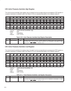
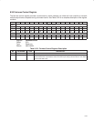
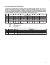
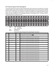
8.34 Isochronous Cycle Timer Register
The isochronous cycle timer register indicates the current cycle number and offset. When the PCI7x21/PCI7x11
controller is cycle master, this register is transmitted with the cycle start message. When the PCI7x21/PCI7x11
controller is not cycle master, this register is loaded with the data field in an incoming cycle start. In the event that
the cycle start message is not received, the fields can continue incrementing on their own (if programmed) to maintain
a local time reference. See Table 8−26 for a complete description of the register contents.
Bit 31 30 29 28 27 26 25 24 23 22 21 20 19 18 17 16
Name Isochronous cycle timer
Type RWU RWU RWU RWU RWU RWU RWU RWU RWU RWU RWU RWU RWU RWU RWU RWU
Default X X X X X X X X X X X X X X X X
Bit 15 14 13 12 11 10 9 8 7 6 5 4 3 2 1 0
Name Isochronous cycle timer
Type RWU RWU RWU RWU RWU RWU RWU RWU RWU RWU RWU RWU RWU RWU RWU RWU
Default X X X X X X X X X X X X X X X X
Register: Isochronous cycle timer
Offset: F0h
Type: Read/Write/Update
Default: XXXX XXXXh
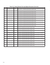
Table 8−26. Isochronous Cycle Timer Register Description
BIT FIELD NAME TYPE DESCRIPTION
31−25 cycleSeconds RWU This field counts seconds [rollovers from bits 24−12 (cycleCount field)] modulo 128.
24−12 cycleCount RWU This field counts cycles [rollovers from bits 11−0 (cycleOffset field)] modulo 8000.
11−0 cycleOffset RWU This field counts 24.576-MHz clocks modulo 3072, that is, 125 µs. If an external 8-kHz clock
configuration is being used, then this field must be cleared to 0s at each tick of the external clock.