


4−7
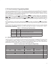
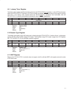
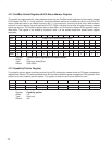
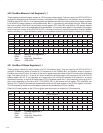
4.9 Latency Timer Register
The latency timer register specifies the latency timer for the PCI7x21/PCI7x11 controller, in units of PCI clock cycles.
When the PCI7x21/PCI7x11 controller is a PCI bus initiator and asserts FRAME
, the latency timer begins counting
from zero. If the latency timer expires before the PCI7x21/PCI7x11 transaction has terminated, then the
PCI7x21/PCI7x11 controller terminates the transaction when its GNT
is deasserted.
Bit 7 6 5 4 3 2 1 0
Name Latency timer
Type RW RW RW RW RW RW RW RW
Default 0 0 0 0 0 0 0 0
Register: Latency timer
Offset: 0Dh
Type: Read/Write
Default: 00h
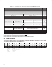
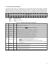
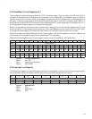
4.10 Header Type Register
The header type register returns 82h when read, indicating that the PCI7x21/PCI7x11 functions 0 and 1 configuration
spaces adhere to the CardBus bridge PCI header. The CardBus bridge PCI header ranges from PCI registers
00h−7Fh, and 80h−FFh is user-definable extension registers.
Bit 7 6 5 4 3 2 1 0
Name Header type
Type R R R R R R R R
Default 1 0 0 0 0 0 1 0
Register: Header type
Offset: 0Eh (Functions 0, 1)
Type: Read-only
Default: 82h
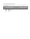
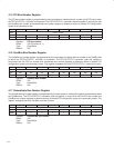
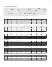
4.11 BIST Register
Because the PCI7x21/PCI7x11 controller does not support a built-in self-test (BIST), this register returns the value
of 00h when read.
Bit 7 6 5 4 3 2 1 0
Name BIST
Type R R R R R R R R
Default 0 0 0 0 0 0 0 0
Register: BIST
Offset: 0Fh (Functions 0, 1)
Type: Read-only
Default: 00h