


6−7
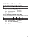
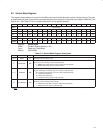
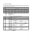
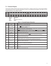
6.5 Socket Control Register
This register provides control of the voltages applied to the socket V
PP
and V
CC
. The PCI7x21/PCI7x11 controller
ensures that the socket is powered up only at acceptable voltages when a CardBus card is inserted. See Table 6−6
for a complete description of the register contents.
Bit 31 30 29 28 27 26 25 24 23 22 21 20 19 18 17 16
Name Socket control
Type R R R R R R R R R R R R R R R R
Default 0 0 0 0 0 0 0 0 0 0 0 0 0 0 0 0
Bit 15 14 13 12 11 10 9 8 7 6 5 4 3 2 1 0
Name Socket control
Type R R R R R R RW R RW RW RW RW R RW RW RW
Default 0 0 0 0 0 1 0 0 0 0 0 0 0 0 0 0
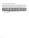
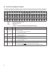
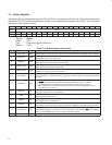
Register: Socket control
Offset: CardBus Socket Address + 10h
Type: Read-only, Read/Write
Default: 0000 0400h
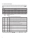
Table 6−6. Socket Control Register Description
BIT SIGNAL TYPE FUNCTION
31−11 RSVD R These bits return 0s when read.
10 RSVD R This bit returns 1 when read.
9−8 RSVD R These bits return 0s when read.
7 STOPCLK RW
This bit controls how the CardBus clock run state machine decides when to stop the CardBus clock
to the CardBus card:
0 = The CardBus CLKRUN
protocol can only attempt to stop/slow the CaredBus clock if the
sockethas been idle for 8 clocks and the PCI CLKRUN
protocol is preparing to stop/slow the
PCI bus clock.
1 = The CardBus CLKRUN
protocol can only attempt to stop/slow the CaredBus clock if the
socket has been idle for 8 clocks, regardless of the state of the PCI CLKRUN
signal.
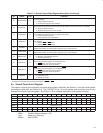
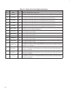
6−4 † VCCCTRL RW
V
CC
control. These bits are used to request card V
CC
changes.
000 = Request power off (default) 100 = Request V
CC
= X.X V
001 = Reserved 101 = Request V
CC
= Y.Y V
010 = Request V
CC
= 5 V 110 = Reserved
011 = Request V
CC
= 3.3 V 111 = Reserved
3 RSVD R This bit returns 0 when read.
2−0 † VPPCTRL RW
V
PP
control. These bits are used to request card V
PP
changes.
000 = Request power off (default) 100 = Request V
PP
= X.X V
001 = Request V
PP
= 12 V 101 = Request V
PP
= Y.Y V
010 = Request V
PP
= 5 V 110 = Reserved
011 = Request V
PP
= 3.3 V 111 = Reserved
†
One or more bits in the register are PME context bits and can be cleared only by the assertion of GRST
when PME is enabled. If PME is not
enabled, then this bit is cleared by the assertion of PRST
or GRST.