


3−25
3.8.9 PCI Power Management
3.8.9.1 CardBus Power Management (Functions 0 and 1)
The PCI Bus Power Management Interface Specification for PCI to CardBus Bridges establishes the infrastructure
required to let the operating system control the power of PCI functions. This is done by defining a standard PCI
interface and operations to manage the power of PCI functions on the bus. The PCI bus and the PCI functions can
be assigned one of seven power-management states, resulting in varying levels of power savings.
The seven power-management states of PCI functions are:
• D0-uninitialized − Before controller configuration, controller not fully functional
• D0-active − Fully functional state
• D1 − Low-power state
• D2 − Low-power state
• D3
hot
− Low-power state. Transition state before D3
cold
• D3
cold
− PME signal-generation capable. Main power is removed and VAUX is available.
• D3
off
− No power and completely nonfunctional
NOTE 1: In the D0-uninitialized state, the PCI7x21/PCI7x11 controller does not generate PME and/or interrupts. When bits 0 (IO_EN) and 1
(MEM_EN) of the command register (PCI offset 04h, see Section 4.4) are both set, the PCI7x21/PCI7x11 controller switches the state
to D0-active. Transition from D3
cold
to the D0-uninitialized state happens at the deassertion of PRST
. The assertion of GRST forces
the controller to the D0-uninitialized state immediately.
NOTE 2: The PWR_STATE bits (bits 1−0) of the power-management control/status register (PCI offset A4h, see Section 4.44) only code for four
power states, D0, D1, D2, and D3
hot
. The differences between the three D3 states is invisible to the software because the controller
is not accessible in the D3
cold
or D3
off
state.
Similarly, bus power states of the PCI bus are B0−B3. The bus power states B0−B3 are derived from the device power
state of the originating bridge device.
For the operating system (OS) to manage the controller power states on the PCI bus, the PCI function must support
four power-management operations. These operations are:
• Capabilities reporting
• Power status reporting
• Setting the power state
• System wake-up
The OS identifies the capabilities of the PCI function by traversing the new capabilities list. The presence of
capabilities in addition to the standard PCI capabilities is indicated by a 1 in bit 4 (CAPLIST) of the status register (PCI
offset 06h, see Section 4.5).
The capabilities pointer provides access to the first item in the linked list of capabilities. For the PCI7x21/PCI7x11
controller, a CardBus bridge with PCI configuration space header type 2, the capabilities pointer is mapped to an offset
of 14h. The first byte of each capability register block is required to be a unique ID of that capability. PCI power
management has been assigned an ID of 01h. The next byte is a pointer to the next pointer item in the list of
capabilities. If there are no more items in the list, then the next item pointer must be set to 0. The registers following
the next item pointer are specific to the capability of the function. The PCI power-management capability implements
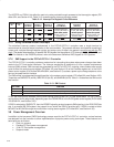
the register block outlined in Table 3−15.
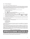
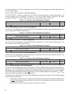
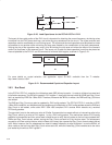
Table 3−15. Power-Management Registers
REGISTER NAME OFFSET
Power-management capabilities Next item pointer Capability ID A0h
Data Power-management control/status register bridge support extensions Power-management control/status (CSR) A4h
The power-management capabilities register (PCI offset A2h, see Section 4.43) provides information on the
capabilities of the function related to power management. The power-management control/status register (PCI offset
A4h, see Section 4.44) enables control of power-management states and enables/monitors power-management
events. The data register is an optional register that can provide dynamic data.