


2−24
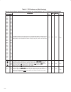
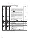
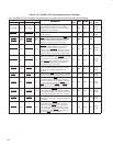
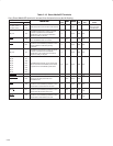
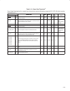
Table 2−14. CardBus PC Card Interface Control Terminals
If any CardBus PC Card interface control terminal is unused, then the terminal may be left floating.
SKT A TERMINAL SKT B TERMINAL
†
DESCRIPTION
I/O
INPUT
OUTPUT
PU/
POWER
NAME NO. NAME NO.
DESCRIPTION
I/O
TYPE
INPUT OUTPUT
PU/
PD
POWER
RAIL
A_CAUDIO A02 B_CAUDIO C17
CardBus audio. CAUDIO is a digital input signal from
a PC Card to the system speaker. The controller
supports the binary audio mode and outputs a binary
signal from the card to SPKROUT.
I PCII4 PCIO4 PU3
V
CCA
/
V
CCB
A_CBLOCK
E10
B_CBLOCK
J19
CardBus lock. CBLOCK is used to gain exclusive
access to a target.
I/O PCII4 PCIO4 PU3
V
CCA
/
V
CCB
A_CCD1
C15
B_CCD1
N13
CardBus detect 1 and CardBus detect 2. CCD1 and
CCD2 are used in conjunction with CVS1 and CVS2
I
TTLI2
PU4
A_CCD1
A_CCD2
C15
E05
B_CCD1
B_CCD2
N13
B17
CCD2 are used in conjunction with CVS1 and CVS2
to identify card insertion and interrogate cards to
determine the operating voltage and card type.
I TTLI2 PU4
A_CDEVSEL
C09
B_CDEVSEL
H19
CardBus device select. The controller asserts
CDEVSEL
to claim a CardBus cycle as the target
device. As a CardBus initiator on the bus, the
controller monitors CDEVSEL
until a target responds.
If no target responds before timeout occurs, then the
controller terminates the cycle with an initiator abort.
I/O PCII4 PCIO4 PU3
V
CCA
/
V
CCB
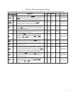
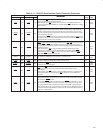
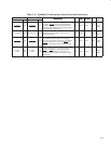
A_CFRAME
C08
B_CFRAME
G19
CardBus cycle frame. CFRAME is driven by the
initiator of a CardBus bus cycle. CFRAME
is asserted
to indicate that a bus transaction is beginning, and
data transfers continue while this signal is asserted.
When CFRAME
is deasserted, the CardBus bus
transaction is in the final data phase.
I/O PCII7 PCIO7
V
CCA
/
V
CCB
A_CGNT
B09
B_CGNT
J15
CardBus bus grant. CGNT is driven by the controller
to grant a CardBus PC Card access to the CardBus
bus after the current data transaction has been
completed.
O PCII7 PCIO7
V
CCA
/
V
CCB
A_CINT
C04
B_CINT
B19
CardBus interrupt. CINT is asserted low by a CardBus
PC Card to request interrupt servicing from the host.
I PCII4 PCIO4 PU3
V
CCA
/
V
CCB
A_CIRDY
B08
B_CIRDY
J13
CardBus initiator ready. CIRDY indicates the ability of
the CardBus initiator to complete the current data
phase of the transaction. A data phase is completed
on a rising edge of CCLK when both CIRDY
and
CTRDY
are asserted. Until CIRDY and CTRDY are
both sampled asserted, wait states are inserted.
I/O PCII4 PCIO4 PU3
V
CCA
/
V
CCB
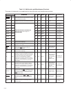
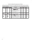
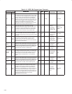
A_CPERR
F10
B_CPERR
J18
CardBus parity error. CPERR reports parity errors
during CardBus transactions, except during special
cycles. It is driven low by a target two clocks following
the data cycle during which a parity error is detected.
I/O PCII4 PCIO4 PU3
V
CCA
/
V
CCB
A_CREQ
E07
B_CREQ
E18
CardBus request. CREQ indicates to the arbiter that
the CardBus PC Card desires use of the CardBus bus
as an initiator.
I PCII4 PCIO4 PU3
V
CCA
/
V
CCB
A_CSERR
B03
B_CSERR
B18
CardBus system error. CSERR reports address parity
errors and other system errors that could lead to
catastrophic results. CSERR
is driven by the card
synchronous to CCLK, but deasserted by a weak
pullup; deassertion may take several CCLK periods.
The controller can report CSERR
to the system by
assertion of SERR
on the PCI interface.
I PCII4 PCIO4 PU3
V
CCA
/
V
CCB
†
These terminals are reserved for the PCI7611 and PCI7411 controllers.