


5−8
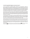
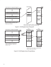
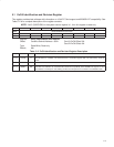
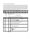
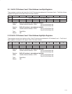
5.4 ExCA Interrupt and General Control Register
This register controls interrupt routing for I/O interrupts as well as other critical 16-bit PC Card functions. See
Table 5−6 for a complete description of the register contents.
Bit 7 6 5 4 3 2 1 0
Name ExCA interrupt and general control
Type RW RW RW RW RW RW RW RW
Default 0 0 0 0 0 0 0 0
Register: ExCA interrupt and general control
Offset: CardBus Socket Address + 803h: Card A ExCA Offset 03h
Card B ExCA Offset 43h
Type: Read/Write
Default: 00h
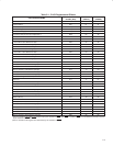
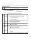
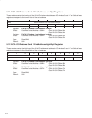
Table 5−6. ExCA Interrupt and General Control Register Description
BIT SIGNAL TYPE FUNCTION
7 RINGEN RW
Card ring indicate enable. Enables the ring indicate function of the BVD1/RI terminals. This bit is encoded
as:
0 = Ring indicate disabled (default)
1 = Ring indicate enabled
6 † RESET RW
Card reset. This bit controls the 16-bit PC Card RESET signal, and allows host software to force a card
reset. This bit affects 16-bit cards only. This bit is encoded as:
0 = RESET signal asserted (default)
1 = RESET signal deasserted.
5 † CARDTYPE RW
Card type. This bit indicates the PC Card type. This bit is encoded as:
0 = Memory PC Card is installed (default)
1 = I/O PC Card is installed
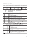
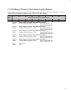
4 CSCROUTE RW
PCI interrupt − CSC routing enable bit. This bit has meaning only if the CSC interrupt routing control bit
(PCI offset 93h, bit 5) is 0. In this case, when this bit is set (high), the card status change interrupts are
routed to PCI interrupts. When low, the card status change interrupts are routed using bits 7−4 in the ExCA
card status-change interrupt configuration register (ExCA offset 805h, see Section 5.6). This bit is encoded
as:
0 = CSC interrupts routed by ExCA registers (default)
1 = CSC interrupts routed to PCI interrupts
If the CSC interrupt routing control bit (bit 5) of the diagnostic register (PCI offset 93h, see Section 4.40)
is set to 1, this bit has no meaning, which is the default case.
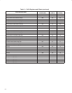
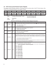
3−0 INTSELECT RW
Card interrupt select for I/O PC Card functional interrupts. These bits select the interrupt routing for I/O
PC Card functional interrupts. This field is encoded as:
0000 = No IRQ selected (default). CSC interrupts are routed to PCI Interrupts. This bit setting is ORed
with bit 4 (CSCROUTE) for backward compatibility.
0001 = IRQ1 enabled
0010 = SMI enabled
0011 = IRQ3 enabled
0100 = IRQ4 enabled
0101 = IRQ5 enabled
0110 = IRQ6 enabled
0111 = IRQ7 enabled
1000 = IRQ8 enabled
1001 = IRQ9 enabled
1010 = IRQ10 enabled
1011 = IRQ11 enabled
1100 = IRQ12 enabled
1101 = IRQ13 enabled
1110 = IRQ14 enabled
1111 = IRQ15 enabled
†
This bit is cleared only by the assertion of GRST
when PME is enabled. If PME is not enabled, then this bit is cleared by the assertion of PRST
or GRST.