


7−17
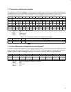
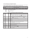
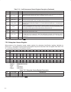
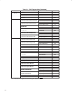
Table 7−20. PCI Miscellaneous Configuration Register Description (Continued)
BIT FIELD NAME TYPE DESCRIPTION
1 ‡
DISABLE_
PCIGATE
RW
When bit 1 is set to 1, the internal PCI clock runs identically with the chip input. This is a test feature
only and must be cleared to 0 (all applications).
0 ‡ KEEP_PCLK RW
When bit 0 is set to 1, the PCI clock is always kept running through the CLKRUN protocol. When this
bit is cleared, the PCI clock can be stopped using CLKRUN
on MFUNC6.
‡
This bit is cleared only by the assertion of GRST
.
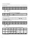
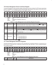
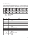
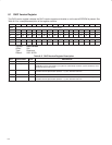
7.24 Link Enhancement Control Register
The link enhancement control register implements TI proprietary bits that are initialized by software or by a serial
EEPROM, if present. After these bits are set to 1, their functionality is enabled only if bit 22 (aPhyEnhanceEnable)
in the host controller control register at OHCI offset 50h/54h (see Section 8.16) is set to 1. See Table 7−21 for a
complete description of the register contents.
Bit 31 30 29 28 27 26 25 24 23 22 21 20 19 18 17 16
Name Link enhancement control
Type R R R R R R R R R R R R R R R R
Default 0 0 0 0 0 0 0 0 0 0 0 0 0 0 0 0
Bit 15 14 13 12 11 10 9 8 7 6 5 4 3 2 1 0
Name Link enhancement control
Type RW R RW RW R RW R RW RW R R R R R RW R
Default 0 0 0 1 0 0 0 0 0 0 0 0 0 0 0 0
Register: Link enhancement control
Offset: F4h
Type: Read/Write, Read-only
Default: 0000 1000h
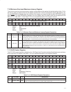
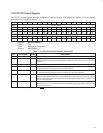
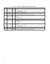
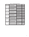
Table 7−21. Link Enhancement Control Register Description
BIT FIELD NAME TYPE DESCRIPTION
31−16 RSVD R Reserved. Bits 31−16 return 0s when read.
15 ‡ dis_at_pipeline RW
Disable AT pipelining. When bit 15 is set to 1, out-of-order AT pipelining is disabled. The default value for this
bit is 0.
14 ‡ RSVD R Reserved. Bit 14 defaults to 0 and must remain 0 for normal operation of the OHCI core.
13−12
‡
atx_thresh RW
This field sets the initial AT threshold value, which is used until the AT FIFO is underrun. When the
PCI7x21/PCI7x11 controller retries the packet, it uses a 2K-byte threshold, resulting in a store-and-forward
operation.
00 = Threshold ~ 2K bytes resulting in a store-and-forward operation
01 = Threshold ~ 1.7K bytes (default)
10 = Threshold ~ 1K bytes
11 = Threshold ~ 512 bytes
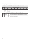
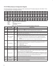
These bits fine-tune the asynchronous transmit threshold. For most applications the 1.7K-byte threshold is
optimal. Changing this value may increase or decrease the 1394 latency depending on the average PCI bus
latency.
Setting the AT threshold to 1.7K, 1K, or 512 bytes results in data being transmitted at these thresholds or
when an entire packet has been checked into the FIFO. If the packet to be transmitted is larger than the AT
threshold, then the remaining data must be received before the AT FIFO is emptied; otherwise, an underrun
condition occurs, resulting in a packet error at the receiving node. As a result, the link then commences a
store-and-forward operation. It waits until it has the complete packet in the FIFO before retransmitting it on
the second attempt to ensure delivery.
An AT threshold of 2K results in a store-and-forward operation, which means that asynchronous data is not
transmitted until an end-of-packet token is received. Restated, setting the AT threshold to 2K results in only
complete packets being transmitted.
Note that this controller always uses a store-and-forward operation when the asynchronous transmit retries
register at OHCI offset 08h (see Section 8.3) is cleared.
‡
These bits are cleared only by the assertion of GRST
.