


2−18
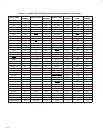
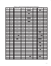
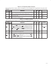
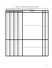
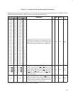
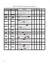
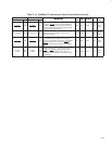
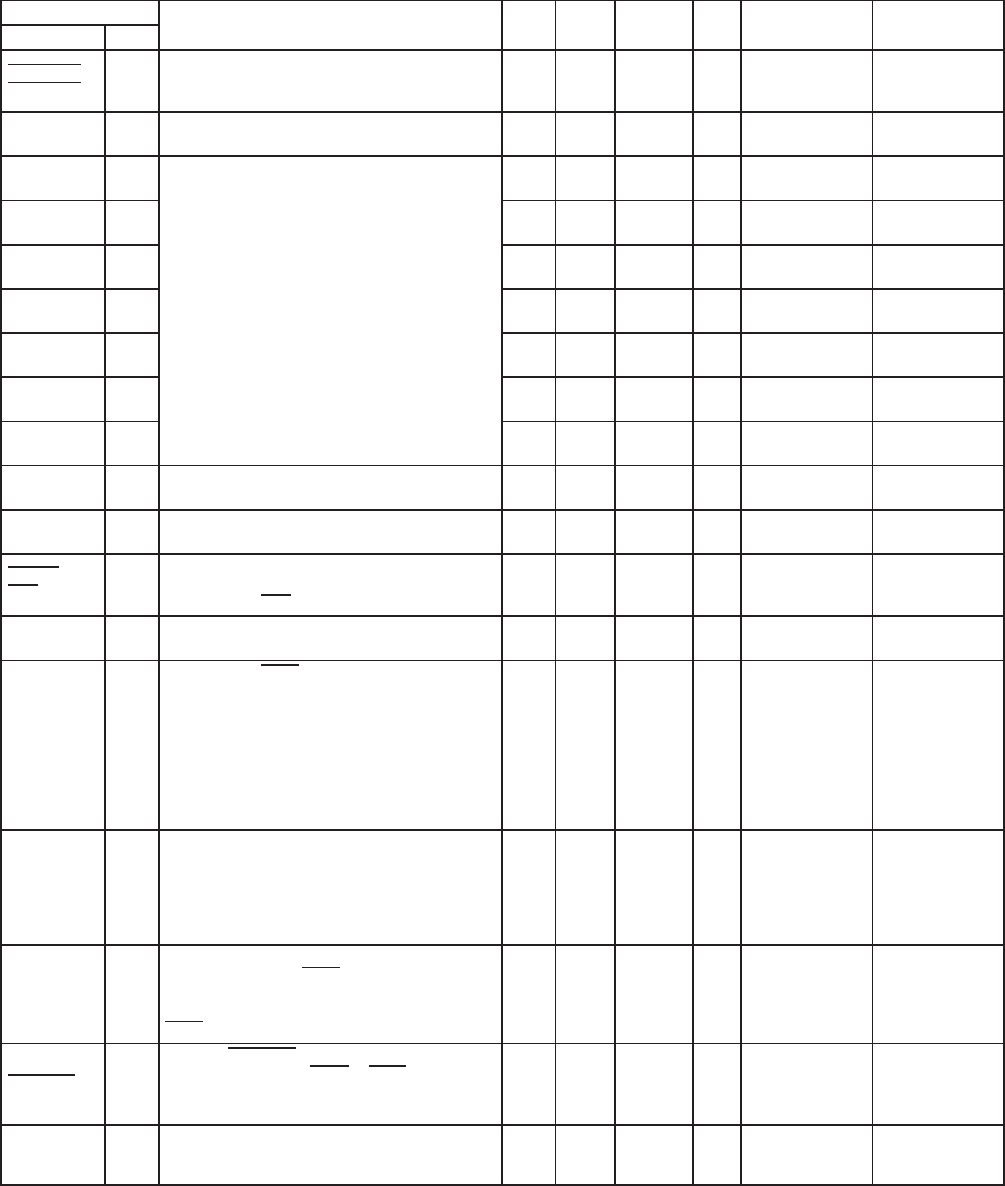
Table 2−9. Multifunction and Miscellaneous Terminals
The power rail designation is not applicable for the multifunction and miscellaneous terminals.
TERMINAL
DESCRIPTION
I/O
INPUT
OUTPUT
PU/
EXTERNAL
PIN STRAPPING
NAME NO.
DESCRIPTION
I/O
TYPE
INPUT OUTPUT
PU/
PD
EXTERNAL
COMPONENTS
PIN STRAPPING
(IF UNUSED)
A_USB_EN
B_USB_EN
E02
E01
USB enable. These output terminals control an
external CBT switch for each socket when an USB
card is inserted into the socket.
O LVCO1 CBT switch Float
CLK_48 M01 A 48-MHz clock must be connected to this terminal. I LVCI1
48 MHz clock
source
MFUNC0 N03 I/O PCII3 PCIO3
10-kΩ to 47-kΩ
pullup resistor
MFUNC1 M05 I/O PCII3 PCIO3
10-kΩ to 47-kΩ
pullup resistor
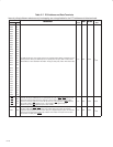
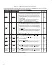
MFUNC2 P01
Multifunction terminals 0−6. See Section 4.36,
I/O PCII3 PCIO3
10-kΩ to 47-kΩ
pullup resistor
MFUNC3 P02
Multifunction terminals 0−6. See Section 4.36,
Multifunction Routing Status Register, for
configuration details.
I/O PCII3 PCIO3
10-kΩ to 47-kΩ
pullup resistor
MFUNC4 P03
configuration details.
I/O PCII3 PCIO3
10-kΩ to 47-kΩ
pullup resistor
MFUNC5 N05 I/O PCII3 PCIO3
10-kΩ to 47-kΩ
pullup resistor
MFUNC6 R01 I/O PCII3 PCIO3
10-kΩ to 47-kΩ
pullup resistor
NC W17
Reserved. This terminal has no connection
anywhere within the package.
Float
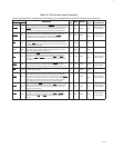
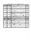
PHY_TEST_
MA
R17
PHY test pin. Not for customer use. It must be pulled
high with a 4.7-kΩ resistor.
I LVCI1 PD1 NA
RI_OUT/
PME
T03
Ring indicate out and power management event
output. This terminal provides an output for
ring-indicate or PME
signals.
O LVCO2
Pullup resistor per
PCI specification
NA
RSVD T19
Reserved. This terminal has no connection
anywhere within the package.
— Float
SCL M03
Serial clock. At PRST, the SCL signal is sampled to
determine if a two-wire serial ROM is present. If the
serial ROM is detected, then this terminal provides
the serial clock signaling and is implemented as
open-drain. For normal operation (a ROM is
implemented in the design), this terminal must be
pulled high to the ROM V
DD
with a 2.7-kΩ resistor.
Otherwise, it must be pulled low to ground with a
220-Ω resistor.
I/O TTLI1 TTLO1
Pullup resistor per
I
2
C specification
(value depends on
EEPROM,
typically 2.7 kΩ)
Tie to GND if not
using EEPROM
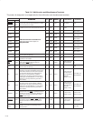
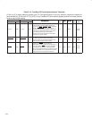
SDA M02
Serial data. This terminal is implemented as
open-drain, and for normal operation (a ROM is
implemented in the design), this terminal must be
pulled high to the ROM V
DD
with a 2.7-kΩ resistor.
Otherwise, it must be pulled low to ground with a
220-Ω resistor.
I/O TTLI1 TTLO1
Pullup resistor per
I
2
C specification
(value depends on
EEPROM,
typically 2.7 kΩ)
Tie to GND if not
using EEPROM
SPKROUT
L07
Speaker output. SPKROUT is the output to the host
system that can carry SPKR
or CAUDIO through the
controller from the PC Card interface. SPKROUT is
driven as the exclusive-OR combination of card
SPKR
//CAUDIO inputs.
O TTLO1
10-kΩ to 47-kΩ
pulldown resistor
10-kΩ to 47-kΩ
pulldown resistor
SUSPEND R02
Suspend. SUSPEND protects the internal registers
from clearing when the GRST
or PRST signal is
asserted. See Section 3.8.6, Suspend Mode, for
details.
I PCII6
10-kΩ to 47-kΩ
pullup resistor
10-kΩ to 47-kΩ
pullup resistor
TEST0 P12
Terminal TEST0 is used for factory test of the
controller and must be connected to ground for
normal operation.
I/O LVCI1 PD1 Tie to GND