


4−28
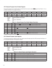
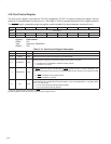
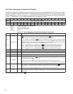
4.38 Card Control Register
The card control register is provided for PCI1130 compatibility. RI_OUT is enabled through this register, and the
enable bit is shared between functions 0 and 1. See Table 4−16 for a complete description of the register contents.
The RI_OUT
signal is enabled through this register, and the enable bit is shared between functions 0 and 1.
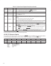
Bit 7 6 5 4 3 2 1 0
Name Card control
Type RW RW RW R R RW RW RW
Default 0 0 0 0 0 0 0 0
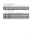
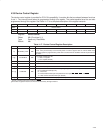
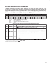
Register: Card control
Offset: 91h
Type: Read-only, Read/Write
Default: 00h
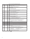
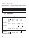
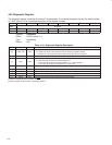
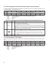
Table 4−16. Card Control Register Description
BIT SIGNAL TYPE FUNCTION
7 ठRIENB RW Ring indicate enable. When this bit is 1, the RI_OUT output is enabled. This bit defaults to 0.
6−3 RSVD RW These bits are reserved. Do not change the value of these bits.
2 ‡ AUD2MUX RW
CardBus audio-to-MFUNC. When this bit is set, the CAUDIO CardBus signal must be routed through an
MFUNC terminal. If this bit is set for both functions, then function 0 is routed.
0 = CAUDIO set to CAUDPWM on MFUNC terminal (default)
1 = CAUDIO is not routed.
1 ‡ SPKROUTEN RW
When bit 1 is set, the SPKR terminal from the PC Card is enabled and is routed to tthe SPKROUT terminal.
The SPKR
signal from socket 0 is XORed with the SPKR signal from socket 1 and sent to SPKROUT. The
SPKROUT terminal drives data only when the SPKROUTEN bit of either function is set. This bit is encoded
as:
0 = SPKR
to SPKROUT not enabled (default)
1 = SPKR
to SPKROUT enabled
0 ‡ IFG RW
Interrupt flag. This bit is the interrupt flag for 16-bit I/O PC Cards and for CardBus cards. This bit is set when
a functional interrupt is signaled from a PC Card interface, and is socket dependent (i.e., not global). Write
back a 1 to clear this bit.
0 = No PC Card functional interrupt detected (default)
1 = PC Card functional interrupt detected
‡
This bit is cleared only by the assertion of GRST
.
§
This bit is global in nature and must be accessed only through function 0.