


8−44
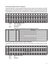
8.46 Isochronous Receive Context Match Register
The isochronous receive context match register starts an isochronous receive context running on a specified cycle
number, filters incoming isochronous packets based on tag values, and waits for packets with a specified sync value.
The n value in the following register addresses indicates the context number (n = 0, 1, 2, 3). See Table 8−35 for a
complete description of the register contents.
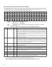
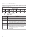
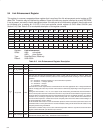
Bit 31 30 29 28 27 26 25 24 23 22 21 20 19 18 17 16
Name Isochronous receive context match
Type RW RW RW RW R RW RW RW RW RW RW RW RW RW RW RW
Default X X X X 0 0 0 X X X X X X X X X
Bit 15 14 13 12 11 10 9 8 7 6 5 4 3 2 1 0
Name Isochronous receive context match
Type RW RW RW RW RW RW RW RW R RW RW RW RW RW RW RW
Default X X X X X X X X 0 X X X X X X X
Register: Isochronous receive context match
Offset: 410Ch + (32 * n)
Type: Read/Write, Read-only
Default: XXXX XXXXh
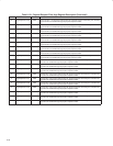
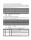
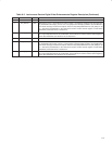
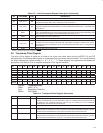
Table 8−35. Isochronous Receive Context Match Register Description
BIT FIELD NAME TYPE DESCRIPTION
31 tag3 RW If bit 31 is set to 1, this context matches on isochronous receive packets with a tag field of 11b.
30 tag2 RW If bit 30 is set to 1, this context matches on isochronous receive packets with a tag field of 10b.
29 tag1 RW If bit 29 is set to 1, this context matches on isochronous receive packets with a tag field of 01b.
28 tag0 RW If bit 28 is set to 1, this context matches on isochronous receive packets with a tag field of 00b.
27 RSVD R Reserved. Bit 27 returns 0 when read.
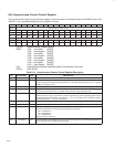
26−12 cycleMatch RW This field contains a 15-bit value corresponding to the two low-order bits of cycleSeconds and the 13-bit
cycleCount field in the cycleStart packet. If cycleMatchEnable (bit 29) in the isochronous receive
context control register (see Section 8.44) is set to 1, then this context is enabled for receives when
the two low-order bits of the isochronous cycle timer register at OHCI offset F0h (see Section 8.34)
cycleSeconds field (bits 31−25) and cycleCount field (bits 24−12) value equal this field (cycleMatch)
value.
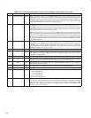
11−8 sync RW This 4-bit field is compared to the sync field of each isochronous packet for this channel when the
command descriptor w field is set to 11b.
7 RSVD R Reserved. Bit 7 returns 0 when read.
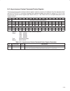
6 tag1SyncFilter RW If bit 6 and bit 29 (tag1) are set to 1, then packets with tag 01b are accepted into the context if the two
most significant bits of the packet sync field are 00b. Packets with tag values other than 01b are filtered
according to bit 28 (tag0), bit 30 (tag2), and bit 31 (tag3) without any additional restrictions.
If this bit is cleared, then this context matches on isochronous receive packets as specified in
bits 28−31 (tag0−tag3) with no additional restrictions.
5−0 channelNumber RW This 6-bit field indicates the isochronous channel number for which this isochronous receive DMA
context accepts packets.