


4−4
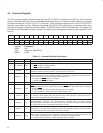
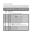
4.4 Command Register
The PCI command register provides control over the PCI7x21/PCI7x11 interface to the PCI bus. All bit functions
adhere to the definitions in the PCI Local Bus Specification (see Table 4−3). None of the bit functions in this register
are shared among the PCI7x21/PCI7x11 PCI functions. Three command registers exist in the PCI7x21/PCI7x11
controller, one for each function. Software manipulates the PCI7x21/PCI7x11 functions as separate entities when
enabling functionality through the command register. The SERR_EN and PERR_EN enable bits in this register are
internally wired OR between the three functions, and these control bits appear to software to be separate for each
function.
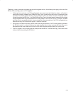
Bit 15 14 13 12 11 10 9 8 7 6 5 4 3 2 1 0
Name Command
Type R R R R R RW R RW R RW RW R R RW RW RW
Default 0 0 0 0 0 0 0 0 0 0 0 0 0 0 0 0
Register: Command
Offset: 04h
Type: Read-only, Read/Write
Default: 0000h
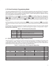
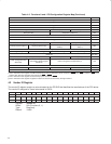
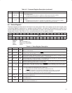
Table 4−3. Command Register Description
BIT
SIGNAL TYPE FUNCTION
15−11 RSVD R Reserved. Bits 15−11 return 0s when read.
10 INT_DISABLE RW
INTx disable. When set to 1, this bit disables the function from asserting interrupts on the INTx signals.
0 = INTx
assertion is enabled (default)
1 = INTx
assertion is disabled
9 FBB_EN R
Fast back-to-back enable. The PCI7x21/PCI7x11 controller does not generate fast back-to-back
transactions; therefore, this bit is read-only. This bit returns a 0 when read.
8 SERR_EN RW
System error (SERR) enable. This bit controls the enable for the SERR driver on the PCI interface. SERR
can be asserted after detecting an address parity error on the PCI bus. Both this bit and bit 6 must be set
for the PCI7x21/PCI7x11 controller to report address parity errors.
0 = Disables the SERR output driver (default)
1 = Enables the SERR
output driver
7 RSVD R Reserved. Bit 7 returns 0 when read.
6 PERR_EN RW
Parity error response enable. This bit controls the PCI7x21/PCI7x11 response to parity errors through the
PERR
signal. Data parity errors are indicated by asserting PERR, while address parity errors are indicated
by asserting SERR
.
0 = PCI7x21/PCI7x11 controller ignores detected parity errors (default).
1 = PCI7x21/PCI7x11 controller responds to detected parity errors.
5 VGA_EN RW
VGA palette snoop. When set to 1, palette snooping is enabled (i.e., the PCI7x21/PCI7x11 controller does
not respond to palette register writes and snoops the data). When the bit is 0, the PCI7x21/PCI7x11
controller treats all palette accesses like all other accesses.
4 MWI_EN R
Memory write-and-invalidate enable. This bit controls whether a PCI initiator device can generate memory
write-and-invalidate commands. The PCI7x21/PCI7x11 controller does not support memory
write-and-invalidate commands, it uses memory write commands instead; therefore, this bit is hardwired
to 0. This bit returns 0 when read. Writes to this bit have no effect.
3 SPECIAL R
Special cycles. This bit controls whether or not a PCI device ignores PCI special cycles. The
PCI7x21/PCI7x11 controller does not respond to special cycle operations; therefore, this bit is hardwired
to 0. This bit returns 0 when read. Writes to this bit have no effect.
2 MAST_EN RW
Bus master control. This bit controls whether or not the PCI7x21/PCI7x11 controller can act as a PCI bus
initiator (master). The PCI7x21/PCI7x11 controller can take control of the PCI bus only when this bit is set.
0 = Disables the PCI7x21/PCI7x11 ability to generate PCI bus accesses (default)
1 = Enables the PCI7x21/PCI7x11 ability to generate PCI bus accesses