


5−22
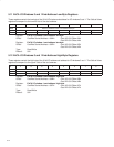
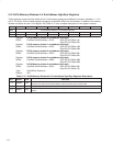
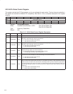
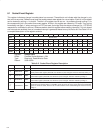
5.20 ExCA Global Control Register
This register controls both PC Card sockets, and is not duplicated for each socket. The host interrupt mode bits in
this register are retained for 82365SL-DF compatibility. See Table 5−15 for a complete description of the register
contents.
Bit 7 6 5 4 3 2 1 0
Name ExCA global control
Type R R R RW RW RW RW RW
Default 0 0 0 0 0 0 0 0
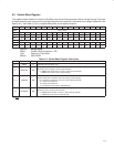
Register: ExCA global control
Offset: CardBus Socket Address + 81Eh: Card A ExCA Offset 1Eh
Card B ExCA Offset 5Eh
Type: Read-only, Read/Write
Default: 00h
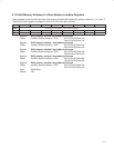
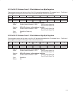
Table 5−15. ExCA Global Control Register Description
BIT SIGNAL TYPE FUNCTION
7−5 RSVD R These bits return 0s when read. Writes have no effect.
4 INTMODEB RW
Level/edge interrupt mode select, card B. This bit selects the signaling mode for the PCI7x21/PCI7x11 host
interrupt for card B interrupts. This bit is encoded as:
0 = Host interrupt is edge mode (default).
1 = Host interrupt is level mode.
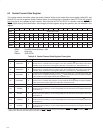
3 INTMODEA RW
Level/edge interrupt mode select, card A. This bit selects the signaling mode for the PCI7x21/PCI7x11 host
interrupt for card A interrupts. This bit is encoded as:
0 = Host interrupt is edge-mode (default).
1 = Host interrupt is level-mode.
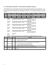
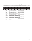
2 ‡ IFCMODE RW
Interrupt flag clear mode select. This bit selects the interrupt flag clear mechanism for the flags in the ExCA
card status change register. This bit is encoded as:
0 = Interrupt flags cleared by read of CSC register (default)
1 = Interrupt flags cleared by explicit writeback of 1
1 ‡ CSCMODE RW
Card status change level/edge mode select. This bit selects the signaling mode for the
PCI7x21/PCI7x11 host interrupt for card status changes. This bit is encoded as:
0 = Host interrupt is edge-mode (default).
1 = Host interrupt is level-mode.
0 ‡ PWRDWN RW
Power-down mode select. When this bit is set to 1, the PCI7x21/PCI7x11 controller is in power-down
mode. In power-down mode the PCI7x21/PCI7x11 card outputs are placed in a high-impedance state until
an active cycle is executed on the card interface. Following an active cycle the outputs are again placed
in a high-impedance state. The PCI7x21/PCI7x11 controller still receives functional interrupts and/or card
status change interrupts; however, an actual card access is required to wake up the interface. This bit is
encoded as:
0 = Power-down mode disabled (default)
1 = Power-down mode enabled
‡
One or more bits in this register are cleared only by the assertion of GRST
.