


10−2
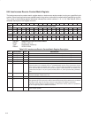
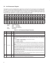
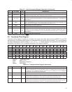
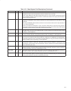
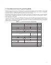
Table 10−2. Base Register Field Descriptions
FIELD SIZE TYPE DESCRIPTION
Physical ID 6 R This field contains the physical address ID of this node determined during self-ID. The physical ID is invalid
after a bus reset until self-ID has completed as indicated by an unsolicited register-0 status transfer.
R 1 R Root. This bit indicates that this node is the root node. The R bit is cleared to 0 by bus reset and is set to 1
during tree-ID if this node becomes root.
CPS 1 R Cable-power-status. This bit indicates the state of the CPS input terminal. The CPS terminal is normally tied
to serial bus cable power through a 400-kΩ resistor. A 0 in this bit indicates that the cable power voltage has
dropped below its threshold for ensured reliable operation.
RHB 1 R/W Root-holdoff bit. This bit instructs the PHY layer to attempt to become root after the next bus reset. The RHB
bit is cleared to 0 by a system (hardware) reset and is unaffected by a bus reset.
IBR 1 R/W Initiate bus reset. This bit instructs the PHY layer to initiate a long (166 µs) bus reset at the next opportunity.
Any receive or transmit operation in progress when this bit is set completes before the bus reset is initiated.
The IBR bit is cleared to 0 after a system (hardware) reset or a bus reset.
Gap_Count 6 R/W Arbitration gap count. This value sets the subaction (fair) gap, arb-reset gap, and arb-delay times. The gap
count can be set either by a write to the register, or by reception or transmission of a PHY_CONFIG packet.
The gap count is reset to 3Fh by system (hardware) reset or after two consecutive bus resets without an
intervening write to the gap count register (either by a write to the PHY register or by a PHY_CONFIG
packet).
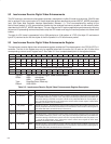
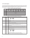
Extended 3 R Extended register definition. For the PCI7x21/PCI7x11 controller, this field is 111b, indicating that the
extended register set is implemented.
Total_Ports 4 R Number of ports. This field indicates the number of ports implemented in the PHY layer. For the
PCI7x21/PCI7x11 controller this field is 2.
Max_Speed 3 R PHY speed capability. For the PCI7x21/PCI7x11 PHY layer this field is 010b, indicating S400 speed
capability.
Delay 4 R PHY repeater data delay. This field indicates the worst case repeater data delay of the PHY layer, expressed
as 144+(delay × 20) ns. For the PCI7x21/PCI7x11 controller this field is 0.
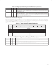
LCtrl 1 R/W Link-active status control. This bit controls the active status of the LLC as indicated during self-ID. The
logical AND of this bit and the LPS active status is replicated in the L field (bit 9) of the self-ID packet. The LLC
is considered active only if both the LPS input is active and the LCtrl bit is set.
The LCtrl bit provides a software controllable means to indicate the LLC active/status in lieu of using the LPS
input.
The LCtrl bit is set to 1 by a system (hardware) reset and is unaffected by a bus reset.
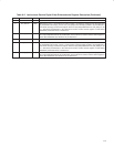
NOTE: The state of the PHY-LLC interface is controlled solely by the LPS input, regardless of the state of the
LCtrl bit. If the PHY-LLC interface is operational as determined by the LPS input being active, received
packets and status information continue to be presented on the interface, and any requests indicated on the
LREQ input are processed, even if the LCtrl bit is cleared to 0.
C 1 R/W Contender status. This bit indicates that this node is a contender for the bus or isochronous resource
manager. This bit is replicated in the c field (bit 20) of the self-ID packet.
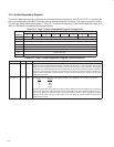
Jitter 3 R PHY repeater jitter. This field indicates the worst case difference between the fastest and slowest repeater
data delay, expressed as (Jitter+1) × 20 ns. For the PCI7x21/PCI7x11 controller, this field is 0.
Pwr_Class 3 R/W Node power class. This field indicates this node power consumption and source characteristics and is
replicated in the pwr field (bits 21−23) of the self-ID packet. This field is reset to the state specified by the
PC0−PC2 input terminals upon a system (hardware) reset and is unaffected by a bus reset. See Table 10−9.
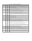
Watchdog 1 R/W Watchdog enable. This bit, if set to 1, enables the port event interrupt (Port_event) bit to be set whenever
resume operations begin on any port. This bit is cleared to 0 by system (hardware) reset and is unaffected by
bus reset.