


8−42
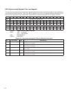
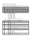
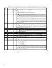
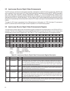
Table 8−34. Isochronous Receive Context Control Register Description (Continued)
BIT FIELD NAME TYPE DESCRIPTION
29 cycleMatchEnable RSCU When bit 29 is set to 1 and the 13-bit cycleMatch field (bits 24−12) in the isochronous receive context
match register (See Section 8.46) matches the 13-bit cycleCount field in the cycleStart packet, the
context begins running. The effects of this bit, however, are impacted by the values of other bits in
this register. Once the context has become active, hardware clears this bit. The value of this bit must
not be changed while bit 10 (active) or bit 15 (run) is set to 1.
28 multiChanMode RSC When bit 28 is set to 1, the corresponding isochronous receive DMA context receives packets for
all isochronous channels enabled in the isochronous receive channel mask high register at OHCI
offset 70h/74h (see Section 8.19) and isochronous receive channel mask low register at OHCI offset
78h/7Ch (see Section 8.20). The isochronous channel number specified in the isochronous receive
context match register (see Section 8.46) is ignored.
When this bit is cleared, the isochronous receive DMA context receives packets for the single
channel specified in the isochronous receive context match register (see Section 8.46). Only one
isochronous receive DMA context may use the isochronous receive channel mask registers (see
Sections 8.19, and 8.20). If more than one isochronous receive context control register has this bit
set, then the results are undefined. The value of this bit must not be changed while bit 10 (active)
or bit 15 (run) is set to 1.
27 dualBufferMode RSC When bit 27 is set to 1, receive packets are separated into first and second payload and streamed
independently to the firstBuffer series and secondBuffer series as described in Section 10.2.3 in the
1394 Open Host Controller Interface Specification. Also, when bit 27 is set to 1, both bits 28
(multiChanMode) and 31 (bufferFill) are cleared to 0. The value of this bit does not change when
either bit 10 (active) or bit 15 (run) is set to 1.
26−16 RSVD R Reserved. Bits 26−16 return 0s when read.
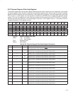
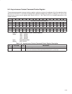
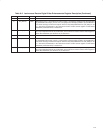
15 run RSCU Bit 15 is set to 1 by software to enable descriptor processing for the context and cleared by software
to stop descriptor processing. The PCI7x21/PCI7x11 controller changes this bit only on a system
(hardware) or software reset.
14−13 RSVD R Reserved. Bits 14 and 13 return 0s when read.
12 wake RSU Software sets bit 12 to 1 to cause the PCI7x21/PCI7x11 controller to continue or resume descriptor
processing. The PCI7x21/PCI7x11 controller clears this bit on every descriptor fetch.
11 dead RU The PCI7x21/PCI7x11 controller sets bit 11 to 1 when it encounters a fatal error, and clears the bit
when software clears bit 15 (run).
10 active RU The PCI7x21/PCI7x11 controller sets bit 10 to 1 when it is processing descriptors.
9−8 RSVD R Reserved. Bits 9 and 8 return 0s when read.
7−5 spd RU This field indicates the speed at which the packet was received.
000 = 100M bits/sec
001 = 200M bits/sec
010 = 400M bits/sec
All other values are reserved.
4−0 event code RU For bufferFill mode, possible values are: ack_complete, evt_descriptor_read, evt_data_write, and
evt_unknown. Packets with data errors (either dataLength mismatches or dataCRC errors) and
packets for which a FIFO overrun occurred are backed out. For packet-per-buffer mode, possible
values are: ack_complete, ack_data_error, evt_long_packet, evt_overrun, evt_descriptor_read,
evt_data_write, and evt_unknown.