


2−29
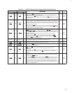
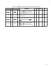
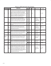
Table 2−19. Smart Card Terminals
†
If any Smart Card terminal is unused, then the terminal may be left floating, except for SC_VCC_5V which must be
connected to 5 V.
TERMINAL
DESCRIPTION
I/O
INPUT
OUTPUT
PU/
POWER
EXTERNAL
NAME NO.
DESCRIPTION
I/O
TYPE
INPUT OUTPUT
PU/
PD
POWER
RAIL
EXTERNAL
PARTS
SC_CD L02
Smart Card card detect. This input is asserted when Smart
Cards are inserted.
I TTLI2 SW2 VCC
SC_CLK K05
Smart Card clock. The controller drives a 3-MHz clock to the
Smart Card interface when enabled.
O PCIO8
22 kΩ resistor to
GND
68 pF capacitor
to GND
SC_DATA L01 Smart Card data input/output I/O PCII5 PCIO5 SW3
SC_OC L03
Smart Card overcurrent. This input comes from the Smart
Card power switch.
I LVCI1 PU2 5 V
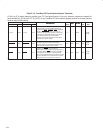
SC_PWR_CTRL L05 Smart Card power control for the Smart Card socket. O LVCO1
Power switch or
FET to turn on
power to FM
socket
SC_FCB K02
Smart Card function code. The controller does not support
synchronous Smart Cards as specified in ISO/IEC 7816-10,
and this terminal is in a high-impedance state.
I PCII5 PCIO5 SW3
SC_GPIO6
SC_GPIO5
SC_GPIO4
SC_GPIO3
SC_GPIO2
SC_GPIO1
SC_GPIO0
H03
J06
J01
J02
J03
J05
J07
Smart Card general-purpose I/O terminals. These signals
can be controlled by firmware and are used as control
signals for an external Smart Card interface chip or level
shifter.
I/O TTLI2 TTLO2 SW2 5 V
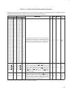
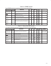
SC_RFU K01
Smart Card reserved. This terminal is in a high-impedance
state.
I PCII5 PCIO5 SW3 5 V
SC_RST K03
Smart Card This signal starts and stops the Smart Card
reset sequence. The controller asserts this reset when
requested by the host.
O PCIO6
SC_VCC_5V K07 Smart Card power terminal PWR
1 kΩ resistor to
5 V
†
These terminals are reserved for the PCI7421 and PCI7411 controllers.