


3−11
• Frequency stability (overtemperature and age): A crystal with ±30 ppm frequency stability is recommended
for adequate margin.
NOTE: The total frequency variation must be kept below ±100 ppm from nominal with some
allowance for error introduced by board and device variations. Trade-offs between frequency
tolerance and stability may be made as long as the total frequency variation is less than
±100 ppm. For example, the frequency tolerance of the crystal may be specified at 50 ppm and
the temperature tolerance may be specified at 30 ppm to give a total of 80 ppm possible
variation due to the crystal alone. Crystal aging also contributes to the frequency variation.
3.6 Serial EEPROM Interface
The PCI7x21/PCI7x11 controller has a dedicated serial bus interface that can be used with an EEPROM to load
certain registers in the PCI7x21/PCI7x11 controller. The EEPROM is detected by a pullup resistor on the SCL
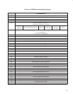
terminal. See Table 3−9 for the EEPROM loading map.
3.6.1 Serial-Bus Interface Implementation
The PCI7x21/PCI7x11 controller drives SCL at nearly 100 kHz during data transfers, which is the maximum specified
frequency for standard mode I
2
C. The serial EEPROM must be located at address A0h.
Some serial device applications may include PC Card power switches, card ejectors, or other devices that may
enhance the user’s PC Card experience. The serial EEPROM device and PC Card power switches are discussed
in the sections that follow.
3.6.2 Accessing Serial-Bus Devices Through Software
The PCI7x21/PCI7x11 controller provides a programming mechanism to control serial bus devices through software.
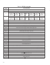
The programming is accomplished through a doubleword of PCI configuration space at offset B0h. Table 3−8 lists
the registers used to program a serial-bus device through software.
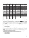
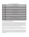
Table 3−8. PCI7x21/PCI7x11 Registers Used to Program Serial-Bus Devices
PCI OFFSET REGISTER NAME DESCRIPTION
B0h Serial-bus data Contains the data byte to send on write commands or the received data byte on read commands.
B1h Serial-bus index
The content of this register is sent as the word address on byte writes or reads. This register is not used
in the quick command protocol.
B2h
Serial-bus slave
address
Write transactions to this register initiate a serial-bus transaction. The slave device address and the
R/W
command selector are programmed through this register.
B3h
Serial-bus control
and status
Read data valid, general busy, and general error status are communicated through this register. In
addition, the protocol-select bit is programmed through this register.
3.6.3 Serial-Bus Interface Protocol
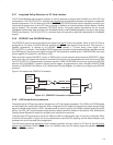
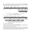
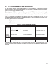
The SCL and SDA signals are bidirectional, open-drain signals and require pullup resistors as shown in Figure 3−4.
The PCI7x21/PCI7x11 controller, which supports up to 100-Kb/s data-transfer rate, is compatible with standard mode
I
2
C using 7-bit addressing.
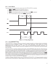
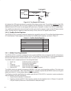
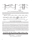
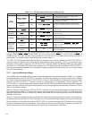
All data transfers are initiated by the serial bus master. The beginning of a data transfer is indicated by a start
condition, which is signaled when the SDA line transitions to the low state while SCL is in the high state, as shown
in Figure 3−7. The end of a requested data transfer is indicated by a stop condition, which is signaled by a low-to-high
transition of SDA while SCL is in the high state, as shown in Figure 3−7. Data on SDA must remain stable during the
high state of the SCL signal, as changes on the SDA signal during the high state of SCL are interpreted as control
signals, that is, a start or a stop condition.