


12−13
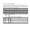
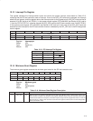
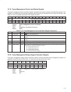
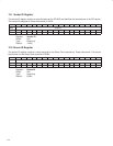
12.19 Power Management Control and Status Register
The power management control and status register implements the control and status of the SD host controller. This
register is not affected by the internally generated reset caused by the transition from the D3
hot
to D0 state. See
Table 12−14 for a complete description of the register contents.
Bit 15 14 13 12 11 10 9 8 7 6 5 4 3 2 1 0
Name Power management control and status
Type RCU R R R R R R RW R R R R R R RW RW
Default 0 0 0 0 0 0 0 0 0 0 0 0 0 0 0 0
Register: Power management control and status
Offset: 84h
Type: Read/Clear, Read/Write, Read-only
Default: 0000h
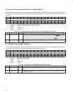
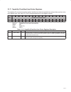
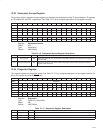
Table 12−14. Power Management Control and Status Register Description
BIT FIELD NAME TYPE DESCRIPTION
15 ‡ PME_STAT RCU PME status. This bit defaults to 0.
14−13 DATA_SCALE R Data scale. This field returns 0s when read, because the SD host controller does not use the data
register.
12−9 DATA_SELECT R Data select. This field returns 0s when read, because the SD host controller does not use the data
register.
8 ‡ PME_EN RW PME enable. Enables PME signaling.
7−2 RSVD R Reserved. Bits 7−2 return 0s when read.
1−0 ‡ PWR_STATE RW Power state. This 2-bit field determines the current power state and sets the SD host controller to a
new power state. This field is encoded as follows:
00 = Current power state is D0.
01 = Current power state is D1.
10 = Current power state is D2.
11 = Current power state is D3
hot
.
‡
One or more bits in this register are cleared only by the assertion of GRST
.
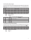
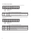
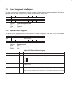
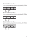
12.20 Power Management Bridge Support Extension Register
The power management bridge support extension register provides extended power-management features not
applicable to the SD host controller; thus, it is read-only and returns 00h when read.
Bit 7 6 5 4 3 2 1 0
Name Power management bridge support extension
Type R R R R R R R R
Default 0 0 0 0 0 0 0 0
Register: Power management bridge support extension
Offset: 86h
Type: Read-only
Default: 00h