


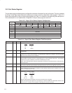

9−3
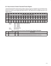
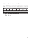
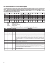
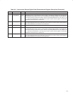
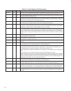
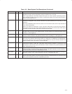
Table 9−2. Isochronous Receive Digital Video Enhancements Register Description (Continued)
BIT FIELD NAME TYPE DESCRIPTION
7−6 RSVD R Reserved. Bits 7 and 6 return 0s when read.
5 DV_Branch1 RSC When bit 5 is set to 1, the isochronous receive context 1 synchronizes reception to the DV frame start
tag in bufferfill mode if input_more.b = 01b, and jumps to the descriptor pointed to by frameBranch if
a DV frame start tag is received out of place. This bit is only interpreted when bit 4 (CIP_Strip1) is set
to 1 and bit 30 (isochHeader) in the isochronous receive context control register at OHCI offset
420h/424h (see Section 8.44) is cleared to 0.
4 CIP_Strip1 RSC When bit 4 is set to 1, the isochronous receive context 1 strips the first two quadlets of payload. This
bit is only interpreted when bit 30 (isochHeader) in the isochronous receive context control register at
OHCI offset 420h/424h (see Section 8.44) is cleared to 0.
3−2 RSVD R Reserved. Bits 3 and 2 return 0s when read.
1 DV_Branch0 RSC When bit 1 is set to 1, the isochronous receive context 0 synchronizes reception to the DV frame start
tag in bufferfill mode if input_more.b = 01b and jumps to the descriptor pointed to by frameBranch if
a DV frame start tag is received out of place. This bit is only interpreted when bit 0 (CIP_Strip0) is set
to 1 and bit 30 (isochHeader) in the isochronous receive context control register at OHCI offset
400h/404h (see Section 8.44) is cleared to 0.
0 CIP_Strip0 RSC When bit 0 is set to 1, the isochronous receive context 0 strips the first two quadlets of payload. This
bit is only interpreted when bit 30 (isochHeader) in the isochronous receive context control register at
OHCI offset 400h/404h (see Section 8.44) is cleared to 0.