


3−6
3.5.1 PC Card Insertion/Removal and Recognition
The PC Card Standard (release 8.1) addresses the card-detection and recognition process through an interrogation
procedure that the socket must initiate on card insertion into a cold, nonpowered socket. Through this interrogation,
card voltage requirements and interface (16-bit versus CardBus) are determined.
The scheme uses the card-detect and voltage-sense signals. The configuration of these four terminals identifies the
card type and voltage requirements of the PC Card interface.
3.5.2 Low Voltage CardBus Card Detection
The card detection logic of the PCI7x21/PCI7x11 controller includes the detection of Cardbus cards with V
CC
= 3.3
V and V
PP
= 1.8 V. The reporting of the 1.8-V CardBus card (V
CC
= 3.3 V, V
PP
= 1.8 V) is reported through the socket
present state register as follows based on bit 10 (12V_SW_SEL) in the general control register (PCI offset 86h, see
Section 4.31):
• If the 12V_SW_SEL bit is 0 (TPS2228 is used), then the 1.8-V CardBus card causes the 3VCARD bit in the
socket present state register to be set.
• If the 12V_SW_SEL bit is 1 (TPS2226 is used), then the 1.8-V CardBus card causes the XVCARD bit in
the socket present state register to be set.
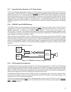
3.5.3 UltraMedia Card Detection
The PCI7x21/PCI7x11 controller is capable of detecting all the UltraMedia devices defined by the PCMCIA Proposal
0262 – MultiMedia Cards, Secure Digital, Memory Stick devices, and Smart Card devices. The detection of these
devices is made possible through circuitry included in the PCI7x21/PCI7x11 controller and the adapters used to
interface these devices with the PC Card/CardBus sockets. No additional hardware requirements are placed on the
system designer in order to support these devices.
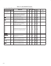
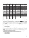
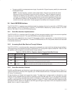
The PC Card Standard addresses the card detection and recognition process through an interrogation procedure that
the socket must initiate upon card insertion into a cold, unpowered socket. Through this interrogation, card voltage
requirements and interface type (16-bit vs. CardBus) are determined. The scheme uses the CD1, CD2, VS1, and VS2
signals (CCD1, CCD2, CVS1, CVS2 for CardBus). A PC Card designer connects these four terminals in a certain
configuration to indicate the type of card and its supply voltage requirements. The encoding scheme for this, defined
in the PC Card Standard, is shown in Table 3−2.